Choosing the Right Antenna |
||
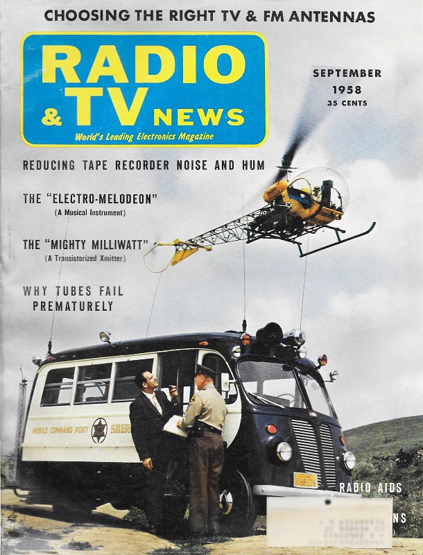
Whereas this "Choosing the Right Antenna" from a 1958 issue of Radio & TV News magazine article concerns television antennas, the information applies generally for any application. Folded dipoles, conicals, Yagis, log periodic, and other types were used by homeowners sometimes desperate to receive a good signal from a far away broadcast station or from a location buried in obstacles (terrain, buildings, water bodies, automobiles, towers, etc.) blocking and reflecting otherwise strong signals, thus causing fading and multipath degradation. You might think the advent of cable and satellite TV, along with Internet access, might have removed the need for rooftop type over-the-air antennas, but it is not so. There are still plenty of people located in rural areas that struggle to get a good signal, as evidenced by RF Cafe visitor Dave Jones, (N1UAV) stacked 9- & 17-element yagi TV antenna project. This is an interesting read. Choosing the Right Antenna
When an antenna has just been wrecked by windstorm, its owner doesn't have to be convinced that he needs a new one. For that matter, a man who has just been struck by a car doesn't have to be coaxed into letting a doctor have a look at him. Nevertheless, many people carry with them for years slowly destructive although undramatic maladies, refusing to seek help short of the point of collapse. Similarly, the American landscape is dotted with thousands of antennas that have, over the years, deteriorated so badly that they still function as symbols of TV receiver ownership, but very little else. "The set isn't what it us to be," the owner of such an antenna may say. He may be maligning an entirely satisfactory receiver that is being robbed of hundred of microvolts of signal or more by a frayed transmission line and corroded antenna elements. The truth never occurs to him. He marvels at his neighbors' newer sets - connected to newer antenna systems - and shakes his head over many things. He may shake his head over the fine pickup by the set next door of that channel 60 miles away. He has never been able to watch it without eye-strain. He may marvel over the absence of ghosts on his favorite channel. Perhaps it makes no sense to him that someone else gets sharp pictures on two or three sets while he can't get good results on one. If he is a hi-fi fan, it annoys him that a nearby friend gets away with excellent FM and TV reception from the same antenna, while he can't do well on TV alone with his. Then there's that channel that came on the air about a year after he got his set (and antenna) - why does everyone else get it well? Or the favored station that comes in good and strong, but is getting spoiled by another transmitter on the same frequency a couple of hundred miles away. Of course, simple aging or the advent of new designs are not the on reasons for unsatisfactory performance from old antennas. The addition of new sets, at the receiving end, or new channels, at the transmitting end - or the relocation of old channels - may be strong factors in antenna inadequacy. This is far from being a complete catalogue of reasons for such inadequacy. The important point is that, when reception difficulties exist, many of the millions of Americans who watch TV and have such problems think in terms of the receiver. In most cases, critical appraisal of the antenna system should be the first consideration. The viewer can be taught that such factors as antenna gain, bandwidth, directivity, rejection of unwanted signals, and others are significant. The "Best" Antenna Even where the role of the antenna is vaguely understood, the set owner will betray serious gaps in his knowledge. "What is the best antenna on the market?" he will ask. We have heard this question countless times. What needs to be done here is a job of education. If the viewer is to learn how much can be done in the way of giving him better reception and what is involved in doing it, his source of information must be the informed service dealer and technician who is capable of spelling out the problems involved. To answer the set owner's key question, he must be informed that, of the many properties an antenna can have, one unit may be outstanding in some but less good in others. For instance, an antenna may show exceptional sensitivity on one, two, or three channels, but not have sufficient bandwidth to do well on others. In a fringe area where one channel, or two close together in frequency, are the only ones available, an antenna like the one noted may be an excellent choice.
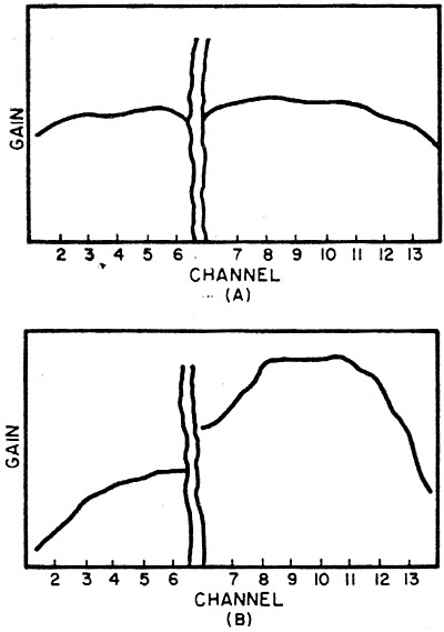
Fig. 1 - A broad-band v.h.f. antenna may have good response (A) on all channels. However, local conditions may call for an antenna with superior response on one or two channels (B). In a metropolitan area however, where many strong signals are available over a wide range of frequencies, a less sensitive antenna with greater bandwidth would be a better choice. Simple diagrams, like the ones comparing two types of frequency response in Fig. 1, can be used to get the point across. Such graphs are plentiful in manufacturers' literature. Points made in this way are important in conveying the information that, alas, there is no such thing as a single "best" antenna. However, there are such things as antennas best suited for particular applications, once these are understood. A point a little harder to make, but also of great importance, is the fact that special reception problems are less likely to be solved far removed from the site than they are by informed professionals on the scene. The sum of local experience is generally the best guide. The local technician or dealer has had as much experience with the peculiarities of his service area as anyone else is likely to. The area distributor also becomes familiar with the local situation, drawing on the combined experience of dealers and technicians in his vicinity. Where problems are severe, the field representatives of antenna manufacturers also get into the act. This combination is the viewer's best bet for improved results. Basic Antenna Types Before considering reception problems, it is well to discuss the conventional antenna designs in common use. There are also many special designs, or units using the basic configurations in special form, or combining basic types. Nevertheless, it is a fact that most installations in existence involve the standard units. The simplest antenna, in appearance at any rate, is the indoor "rabbit ears" type, which looks like an upright V. Its relative insensitivity is no problem where signal is plentiful, as in many metropolitan locations. It picks up well from front and rear, receiving over a wide angle in each case. Where available channels come in strong from different directions, this may be an advantage. However, this may make it hard to explain to a set owner in such a location why he may not be able to get the best results with such a pickup device. If his reception suffers from serious ghosts on one or more channels, he can be told something about the nature of delayed, reflected signals quite simply and why they are more prevalent where he is located. He can also understand why an antenna that discriminates against such unwanted signals may be more advantageous. A rough sketch of the narrow pickup pattern of another antenna type (Fig. 2A) compared to the broadly bi-directional pattern of his basic dipole (Fig. 2B) tells the story. Nevertheless, there are many cases where one version or another of the simple indoor unit is quite adequate. The author knows of a community, located on high ground some 20 miles from a large city, where most residents use indoor antennas. Since all transmissions from the city are roughly in the same direction from this site, there is no need to re-orient the indoor dipole when switching channels. Since there are no other transmitters close enough to pour unwanted signal into this area on the channels received, there is no interference problem. Here is an excellent illustration of the thesis that the particular area determines the "best" antenna type! Several variations on the basic indoor dipole provide flexibility that may come in handy in some situations. An impedance matching element is often included to provide best transfer of signal from antenna to set. This may be fixed or variable. A selector switch may be present to optimize impedance or resonance for individual channels or to switch additional elements in or out for best reception. Folded Dipoles
(A) The inline antenna, which uses a high-band folded dipole and a similar low-band dipole. Another "high" and "low" dipole antenna is the "piggy back," shown on page 37. (B) A two-bay, stacked version of the 4-element conical, also using 4-element reflectors. (C) A single 6-element or "fan" conical, with a horizontal dipole reflector. Many popular outdoor antennas use two folded dipoles as the principal elements-a small one for the high v.h.f. channels and a larger one for the lower portion of the band. Additional directors or reflectors may be used to sharpen the directivity or pickup pattern and to increase gain. One version is the familiar "piggy back," in which the shorter dipole for channels 7 to 13 is at the top of the mast, with the longer one for channels 2 to 6 below it. This type will generally be most sensitive in the forward direction, but shows variation in this respect from one channel to another. Exactly predicting its characteristics from one channel to another is virtually impossible since these traits will vary due to small mechanical or electrical design differences from one manufacturer to another. This may be said of many basic antenna types. A sometime advantage of this type is the fact that the two dipoles may be oriented independently of each other, which can be useful where available transmissions come from different directions. Like most "high" and "low" combinations, the "piggy back" is not specifically designed for use on the FM band, which is located above channel 6. In another twin-dipole antenna, the "inline" type, the larger, low-band folded dipole is to the rear of the high-band dipole, with a single dipole reflector to the rear of both. Sensitivity and directivity are fairly uniform over both v.h.f. bands, making this type a good choice where several transmitters operating over a wide spread of frequencies arrive from pretty much the same direction. Conicals The conical family of antennas comprises several versions. One basic type uses four elements in the form of an X. In others, six elements are used in a "fan" arrangement. The reflector, to the rear of the antenna, may consist of a single horizontal dipole, another X or fan similar to the forward portion, or a screen. In general, these receptors show increasing gain as they go up in channel or frequency. For this reason, they may be good choices in areas where signals tend to be somewhat weaker on the upper channels than on the lower band. Since these antennas are sensitive in the region between the two v.h.f. bands, they often appeal to people interested in getting FM reception from the same antenna used for TV. "V" Antennas The V-type antennas in popular use fall into two general groups. In the "arrow" type, the forward end of the antenna is a V whose open end faces the direction of transmission. The rear of the antenna is another V faced the same way. In another version, one V is mounted above the other on the mast. While most other antenna types can be stacked for increased gain, this stacked-V arrangement is generally designed and made available as a single, matched unit. These types are like the conicals in that they tend to give increased gain as we go up in channel or frequency. At the lowest v.h.f. range they tend to pick up somewhat from the rear, being slightly bi-directional. While this would constitute an undesirable front-to-back ratio at the bottom of the TV band in some applications, it could be an advantage where it is desired to pick up a low-frequency channel from one direction and a high-frequency transmission from another, possibly eliminating the need for a rotator. Also, like the conicals, the V antennas do well in the FM band. Where one wishes to pick up a u.h.f. station of reasonably good signal strength in addition to regular v.h.f. reception, a V unit may prove a good all-purpose, single choice. Yagis KKnown for their high sensitivity and sharp directivity patterns, yagi antennas are generally associated with fringe-area reception. Their high front-to-back and front-to-side ratios make them useful for suppressing undesired signals arriving from directions other than the one from which reception is sought. However, conventional yagis, since they have restricted bandwidth, are not recommended for all-channel use. At the low v.h.f. band, standard yagis will pick up one or perhaps two adjacent channels with good results. In the higher v.h.f. band, some are broad enough to pick up more than two adjacent channels. In the u.h.f. band, some broad-banded yagis are available to pick up a number of channels over a given portion of this spectrum. Some special designs based on the yagi principle are intended to provide broad-band operation while retaining the other features of conventional yagis. The standard units are obviously good choices in outlying areas where one channel is barely available, or perhaps two adjacent ones. U.H.F. Antennas
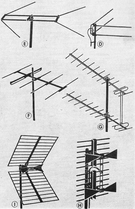
(D) One version of the stacked-V. (E) The flying-V or arrow antenna. (F) A 5-element v.h.f. single-channel yagi. (G) Two u.h.f. yagis, stacked for higher gain. The presence of additional elements in each yagi also increases sensitivity. (H) A pair of u.h.f. bow-ties with a screen reflector. (I) A corner--reflector antenna for u.h.f. Apart from the u.h.f. yagis just mentioned, there are other standard types especially suited to u.h.f. reception. Most popular are the "bow-ties" and corner reflectors. The bow-tie is essentially a broad-banded dipole, backed up by a screen-type reflector. The corner reflector uses a dipole element similar to a bent bow-tie, and its rear reflector screen is also bent, into a V shape, with the fold in the screen running horizontally. Both of these types are made for general use across the u.h.f. band. Design Variations So much for fundamental antenna types. Special types for particular needs exist in such profusion and variety that exhaustive treatment will not be attempted. The design philosophy that marks most of these is the attempt to retain characteristics found in fringe-area antennas, such as high sensitivity, sharp directivity, good front-to-back and front-to-side ratios, while obtaining coverage over as broad a band of frequencies as possible. The extra gain needed in the fringe can often be provided by stacking two or more units of conventional design. However, the increase in sensitivity is not a simple linear function of the number of antennas stacked. Additional gain provided becomes less with each new unit added and matching problems increase. It is generally not advisable to stack more than four antennas. In areas where available signal is extremely weak, it may be necessary to begin with high-gain types and then attempt stacking. Also, stacking presents certain physical problems that will be noted later. Of the special designs, some represent adaptations and combinations of conventional units and others are represented as working on entirely different principles. The best way to assess their characteristics in terms of particular needs is to check the descriptive literature available for these units, including specifications. A check with the local distributor's knowledge of the experience technicians in the vicinity have had with these units, and with the opinion of manufacturers' field representatives, are also useful in reaching a decision. Reception Problems With the great variety of antennas available, how does one make a choice? The viewer must first decide on what kind of reception he wants and, short of that, what he may have to settle for. He must work this out with his service dealer in order for both to work in the desired direction with mutual understanding. This is where the dealer's presentation of the existing problems in understandable form becomes important. If TV-only v.h.f. reception is desired, immediately one may discard antennas that do well in the FM range if they sacrifice performance on TV. Some of the specific problems of combined TV - FM or v.h.f.-u.h.f. reception have already been acknowledged in the discussion of antenna-type characteristics. Where a wide range of frequencies is desired but weak signals are available, the choice between stacking broad-band units or using different types to break up the spectrum desired can only be made on the basis of local experience and experimentation. The angle over which sensitivity is desired will also determine whether broad-band, narrow-band, or separate, differently oriented antennas are used or whether a rotator is desirable. If a color-TV receiver is a present or future consideration, the gain requirement may become more important and linearity of response over individual channels must also be considered. Additional gain requirements must also be considered where more than one receiver is going to be fed from the same antenna system. In many cases, serious interference originates from some local source such as a nearby hospital, industrial plant, or other installation using equipment that may radiate r.f. Fortunately, where this occurs, the point from which such interference originates is seldom in the same horizontal plane as the desired signal. An antenna whose pickup pattern is sharp in the vertical direction would be helpful in discriminating against such undesired r.f. Vertical stacking usually improves the vertical directivity characteristic, even in the case of ordinary antennas. While we have scarcely covered all possible reception problems, at least we have indicated how they can be handled with known antenna techniques. Physical Considerations
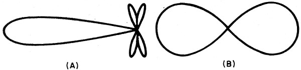
Fig. 2 - A sharply directional sensitivity pattern (A) will provide superior gain and discriminate against unwanted signal from the wrong direction. A broadly bi-directional pattern (B) will pick up well enough from many directions, but will generally provide less gain.
Fig. 3 - A two-set coupler like one shown can be made up easily. It will maintain impedance match, but signal to each set will be down 6 db. Use non-inductive resistors. While we have dwelt on electrical performance, there are many mechanical factors that must be considered in choosing an antenna. Manufacturers have also learned a great deal over the years about improving durability. Special mixes of aluminum or anodizing are used to safeguard elements against a variety of corrosive weather conditions such as the salt-moisture content in coastal areas, smog, and other impurities found in the air. The important spacing insulation, used in some designs, has been improved so that it is not so sensitive to weathering or the accumulation of foreign deposits. Supporting and bracing of elements to withstand the effects of wind and vibration have also improved over the years. This is important where high winds or heavy snow and ice accumulation are a problem. Where wind is a problem, it may be a good idea to avoid antennas whose elements are disposed in the vertical plane, or vertically stacked arrays, unless they are carefully supported. Ice and snow accumulation, however, will generally be more serious with horizontally disposed units. Auxiliary Equipment Masts, rotators, transmission lines, preamplifiers, mounting hardware, couplers, and the like certainly need careful consideration, but they merit independent treatment. Masts and towers, where extra height is desired, will often depend on the ground area available for their erection. Guying can be used where space is available, but special self-supporting towers may be needed for smaller areas. Many crank-up towers or others of adjustable height are available. These come in handy where, due to layering, special terrain problems, or other effects, signal strength varies erratically with antenna height. In cases like the one just noted, and others where erratic signal availability is encountered, a field-strength meter will be a desirable instrument to use, especially where signals are so low that every last microvolt is eagerly sought. A test receiver is often employed for determining the best point of antenna location and orientation, but this system has drawbacks in critical cases. Due to a.g.c. action and other effects, the relationship between the quality of reception and signal in the antenna is neither linear nor absolute. An antenna arrangement that will provide good performance on the day of installation may be unsatisfactory the following day if the weather changes. Anticipating such variations in signal availability, the field-strength meter can be used to look for an antenna position that will provide some reserve signal beyond the minimum required to produce satisfactory performance at the particular time of installation. A test receiver cannot make this important difference sufficiently apparent. Couplers are available in a variety of resistive or inductive types, or combinations of these two. Primarily, they attempt to maintain good match to the antenna and all receivers involved. They vary with respect to the amount of signal loss they introduce and the isolation between one set and another. If adequate signal is available, a simple, two-set coupler can be made up of four resistors, in the configuration shown in Fig. 3. It will retain the necessary match to the antenna system, but introduces a 6-db loss of signal to each set. It also provides fairly good isolation between sets. Returning to our original premise, there is no such thing as a one best antenna for all uses. Nevertheless, with mutual understanding between service dealer and set owner as to reception goals, much can be achieved. It is true that thousands of people now tolerating unsatisfactory reception can either eliminate their problems entirely or obtain substantial improvement with intelligent application of available methods.
Posted February 17, 2020 |
||
 Poor TV receiver performance? Before blaming
the set find out what a new, properly chosen antenna system will do.
Poor TV receiver performance? Before blaming
the set find out what a new, properly chosen antenna system will do.