The ABCs of Antenna Design
|
||
Before I forget, let me remind you while on the subject of antenna design that beginning January 1, 2022, EZNEC Antenna Software by Roy Lewallen (W7EL) is being offered free of charge. It is inarguably the world's premiere package for amateur radio enthusiasts and is used by many professionals. QST's Joel Hallas (SK) used it extensively as part of his monthly "The Doctor Is In" column. This "ABCs of Antenna Design" article appeared in a 1948 issue of Radio News magazine in an era when nomographs, slide rules, and empirical testing and adjusting were the primary tools of all designers. Digital and analog computers occupied entire wings of buildings and could not calculate results nearly as well as EZNEC can on even a low end Windows 10 computer. The ABCs of Antenna Design
Fig. 8
Fig. 9
Fig. 10
Fig. 11
Fig. 12
Fig. 13
Fig. 14
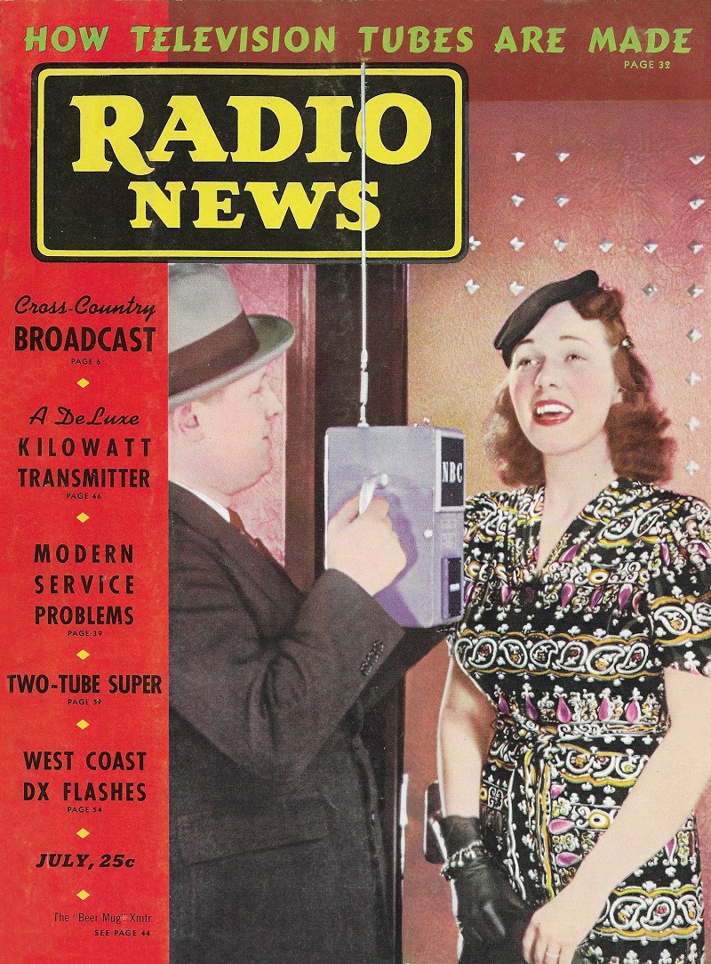
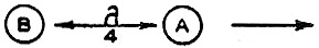
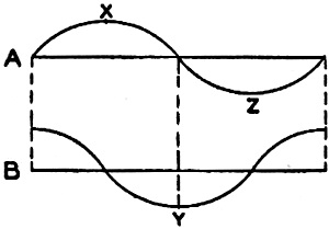
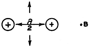
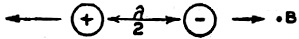
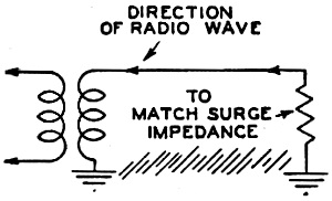
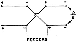
Fig. 15 by I. Queen Completing the series of articles on antenna design, the author discusses the intricacies of directive arrays and how they work. To those hams who have wondered why and how they "got out better" with that signal squisher, this final article will clarify things. Consider now the system of two wires shown in figure 8. We assume we are looking down on two vertical wires. These are two similar vertical antennas, for instance, half-wave doublets. Radiation from A will take place as usual since this wire is supplied with r.f. excitation. B, however, is not fed. The radio field due to A will induce a voltage in B which will oscillate and therefore radiate also. With B approximately a quarter wave length from A, the radiation from the two wires will be favorable for energy propagation in the direction of the arrow. The radiation from B at any instant is 90° out of phase with that from A. Suppose the point X of a wave is transmitted from A (figure 9). It will reach B at the instant that the point Y is being radiated and the two will cancel for this direction. On the other hand, if a point such as Y emanates from B at a certain instant it will arrive at A a quarter of a cycle later and will reinforce the point Z which is being radiated from the aerial A. Antenna B is known as a reflector and because it is not fed with energy it is called a parasitic antenna. If a parasitic antenna is tuned to a higher frequency than the primary radiator and placed with the field of the latter as before, it is found that this unfed wire becomes a director and will aid propagation in its direction while cancelling waves in the backward direction. This is because of the resulting phase changes. Since a conductor of electricity reflects radio waves it is also possible to use a reflector consisting of solid metal arranged in the form of a parabola with the radiator at the focus. This is, of course, practical only at ultra-short wave-lengths. An excellent reflecting system could be the use of several reflecting parasitic antennas and directors as in figure 10, the result being a sharp beam radiation. The distance, between director and antenna should be three-eighths wave-length for maximum focusing of the beam. The distance between reflector and antenna should be one-fourth wave-length. On the ultra-high frequencies the earth becomes an excellent conductor and therefore may act as a reflector unless the height of the radiator is great compared with a wave-length. By increasing the height more than a quarter-wave length, more of the energy is radiated at a low angle to earth, which is desirable. In fact, in accordance with what has been said in the earlier parts of this article, it can be seen that the lower the wave length, the more desirable it is to transmit at a low angle to earth for maximum distance coverage. Antenna Arrays In order to conserve energy and obtain more reliable communication under adverse conditions, it is usual to arrange an antenna system so as to transmit most of the energy in one desired direction. For communication between fixed points, such systems take the form of a great number of antennas erected with the above in mind. In figure 11, there is drawn a system of two radiators fed in phase, and placed one-half wave-length apart. It is plain that a receiving station located broadside to the system (on the perpendicular bisector of the wires) will receive energy in phase from both wires, that is, a strong signal. A receiver on the line joining the two wires, on the other hand, receives no signal. If each wire is fed out of phase with respect to that next to itself, a receiver in a broadside direction receives energy out of phase from each radiator and no signal results. On the line joining the antennas, however, the opposite is true. Each energy radiation is in phase as far as the receiver is concerned and a maximum signal is heard. A number of such radiators may be used, each one-half wave-length from the next in a straight line, and each fed out of phase with the next. This is called an end-fire array. The above principles can be taken advantage of in a number of ways. We may use the broadside array of figure 11 and back it up with a similar array one-quarter wave-length away to form a reflecting array. We may also modify the "V" antenna previously described by adding another "V", alongside it, forming a "W'" which will , transmit a sharp beam in the broadside direction. Another "W" erected a quarter wave-length behind the first would form a powerful reflector. It can be seen that it is possible to secure as sharp and powerful a beam in a given direction as is desired with the cost a limiting factor. An array of wires may be used simply as a unit of a great antenna array. This is practical on the shorter wave-lengths. On the ultra high-frequencies, it also becomes practical to erect the system so that it can be rotated to different directions. Wave Antenna In figure 13 is shown a wave antenna, used especially for receiving. When a radio wave travels in the direction of the arrow towards the receiver a current is being continually induced in the wire, so that by the time it reaches the end, it is of large amplitude. The wire cannot be more than several wave-lengths long, since the current travels slower than the radio wave and in time would be out of phase with it. Other Systems Among other directional systems used is that illustrated in figure 14. Here four - half-wave radiators are fed in phase. The transmission is, of course, broadside to the system, that is towards and away from the reader. A similar system may be erected at a distance of a quarter wave-length as reflector. The in-phase condition is maintained by crossing the feeders between the two horizontal wires. Another useful system for the reception of distant signals is the so-called diversity system. Different receiving antennas (directional or non-directional) are erected at great distances from each other. The energy gathered by each is amplified and detected and then combined to form a single audio signal. Although one antenna may be receiving energy out of phase with another at radio frequency, the a.f. resultants will be in phase. The combined audio frequency energy may then be amplified as usual. This system greatly eliminates fading. Loops The loop type of antenna has been used for years in conjunction with the more sensitive receivers. This is simply a rotatable directional aerial and is used extensively for direction finding on ships and aeroplanes. Because it is practically a closed circuit it does not form a very powerful transmitting antenna. From the illustration of the loop in figure 15 we see that when a wave approaches from direction A, there is a maximum phase difference between the two vertical sides of the loop. (If these two sides were half a wave-length apart we would obtain maximum phase difference and maximum induced voltage.) The above is true also for a wave approaching from B. A wave coming from a direction broadside to the loop causes currents to cancel since they will be in the same direction in both sides of the loop. Rotation of the loop thus shows two possible directions of the transmitter. Because the minimum indication is much sharper than the maximum indication, the former is used as a rule. For direction finding it is essential to know the direction of the transmitter. The loop may be made unilateral as follows. In conjunction with a loop, a vertical antenna is erected. The combined energy is fed into the receiving circuits. Now the current in one side of the loop is always out of phase with that in the other side. Suppose that a station is tuned in at maximum volume using both the loop and the vertical wire. If the loop is now turned 180° the total loop current which before was aiding the vertical wire will now nullify it, and if the energy pickup of each aerial is equal the resultant will be zero. The entire system thus becomes uni-directional. It is only necessary to know which side of the loop always points to the transmitter.
Posted January 7, 2022 |
||