Variable-Voltage Tuning |
|
Have you ever used any of these voltage-variable capacitor (VVC) types: varicaps, epicaps, minicaps, voltacaps, capistors and varactrons? If you answered "no, but I have used varactor diodes," then the more correct answer would have "yes, I have, but by a different name." Construction was similar for all variations. This article from a 1969 issue of Radio-Electronics magazine reports on some of the earliest forms of diodes specifically designed to use a reverse bias on the PN junction to control the effective capacitance of the device for use in frequency tuning circuits. The first uses were for electronically tuning local oscillators in mixing stages, and then for making tunable filters. Capacitance ratios greater than 10:1 with some VVCs allowed tuning over a very wide range. At the time the article was written, there was not universally agreed upon schematic symbol for the VVC, as illustrated in Figure 2. Varactor-tuned television channel selectors made for much smaller tuner assemblies with fewer adjustments for alignment across the entire VHF and UHF bands. Here are some really good photos of the vintage TV channel selectors (see parts 1 and 2, also). Variable-Voltage Tuning: How It Works A new kind of tuning "capacitor" for the new sets By Robert F. Scott Senior Technical Editor
Fig. 1 - Capacitance vs reverse voltage curve for voltage-variable capacitor (VVC). Nominal capacitance is the value obtained with 4 volts of reverse bias.
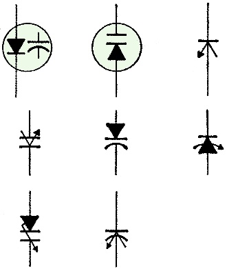
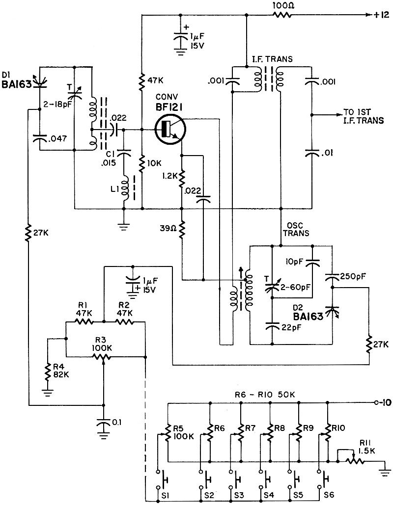
Fig. 2 - There is no common voltage-variable capacitor (VVC) symbol. Here are the most common ones in use. R-E uses the one shown at right in bottom row. During the revolution of radio communications, the galena crystal and spark gap gave way to vacuum tubes and now the vacuum tube is rapidly being replaced by semiconductors. The variable tuning capacitor - which, except for permeability tuning in auto radios, seemed to be forever with us - is now bowing out in favor of a solid-state equivalent. These semiconductors that are replacing the tuning capacitor are generally known as voltage variable capacitance (VVC) diodes, varactors, voltage variable diodes or capacitance diodes and by such trade names as Varicaps, Epicaps, Minicaps, Voltacaps, Capistors and Varactrons. The VVC is a special type of silicon diode that acts like a capacitor when its pn junction is back-biased. The effective capacitance of a diode varies as the formula 1 √V as the voltage across its terminals is varied. The capacitance versus bias voltage curve for a typical VVC diode is shown in Fig. 1. There doesn't seem to be a standard symbol for the VVC. Some of the more common ones are shown in Fig. 2. The earlier VVC's had a low maximum capacitance and a maximum capacitance ratio of around 5.5:1 which limited their use to modulation and afc circuits. Recently, high-Q VVC's have been developed with capacitance ratios greater than 26:1 for a voltage range of 0 to 10 volts. This makes it possible to use them as replacements for the conventional mechanical variable capacitor tuning over as much as a 3 to 1 frequency range of any band on a receiver or signal generator. The VVC offers many advantages over its conventional mechanical equivalent. Among them are: • Small size - they average around 0.1 inch in diameter and 0.3 inch long. • No need for mechanical coupling to dial or drive mechanism. • High-speed tuning. • Greater electrical stability because of immunity to shock and vibration. • No moving parts to wear out or come loose. • Temperature coefficients are known and easily compensated. • Tuning controls (a potentiometer or pushbutton switch to adjust the de bias) can be remote from the tuner. VVC Front-End for AM Radio VVC diodes have been used for tuning and bandswitching in some European TV sets and in some Japanese and European AM/FM radios since around 1964. The front-end (converter) of a pushbutton AM tuner is shown in Fig. 3. It was described in an application note for the BA 163 made by ITT. The BA 163 is a silicon epitaxial diode with a capacitance ratio of greater than 26:1 over a voltage range of 0 to 10 volts. Its Q ranges from 200 (minimum) to 500 (typical) from 150 to 500 kHz at 1 volt and from 300 to 1500 kHz at 10 volts. In the diagram, one BA 163 is connected in series with a 0.047-μF capacitor across the high-impedance winding of a ferrite-type antenna coil. The series capacitor blocks the DC control voltage and prevents it from shorting to ground. Its value is high enough so it does not affect the capacitance range of the VVC. C1-L1 form a trap to reject signals in the set's i.f. range. The oscillator circuit works in the common-base mode with feedback from collector to emitter. The oscillator voltage in the collector circuit is limited (by design) to 1 volt p-p to limit distortion.
Fig. 3 - Front-end of AM tuner designed by ITT to illustrate the use of the BA163 capacitance diode.
Fig. 4 - Basic circuit for adjusting tracking to two VVC diodes.
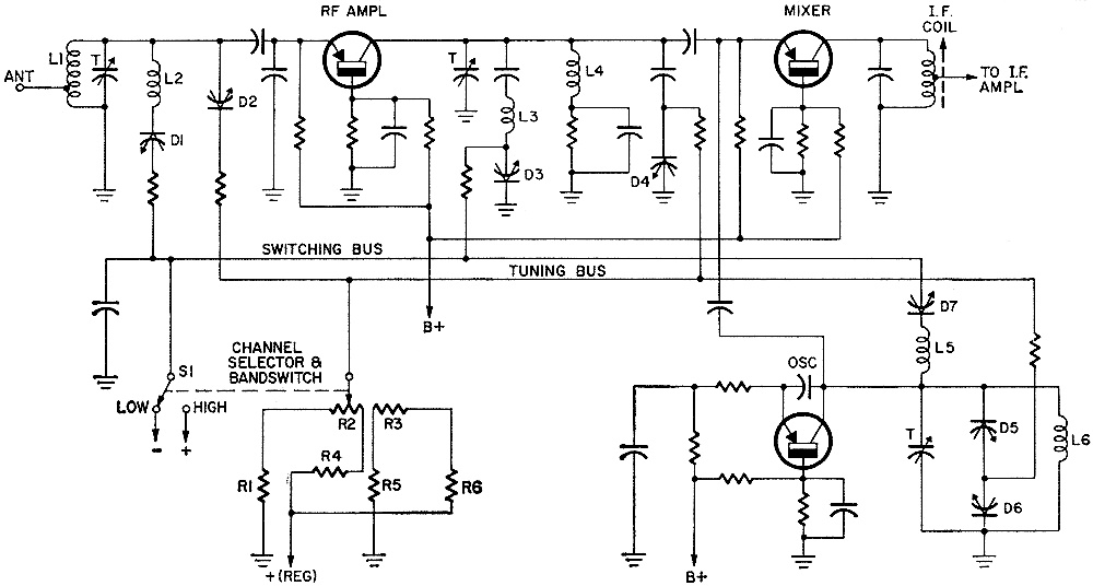
Fig. 5 - Basic circuit of all-channel TV tuner where D2, D4, D5 and D6 tune stations. The others switch bands.
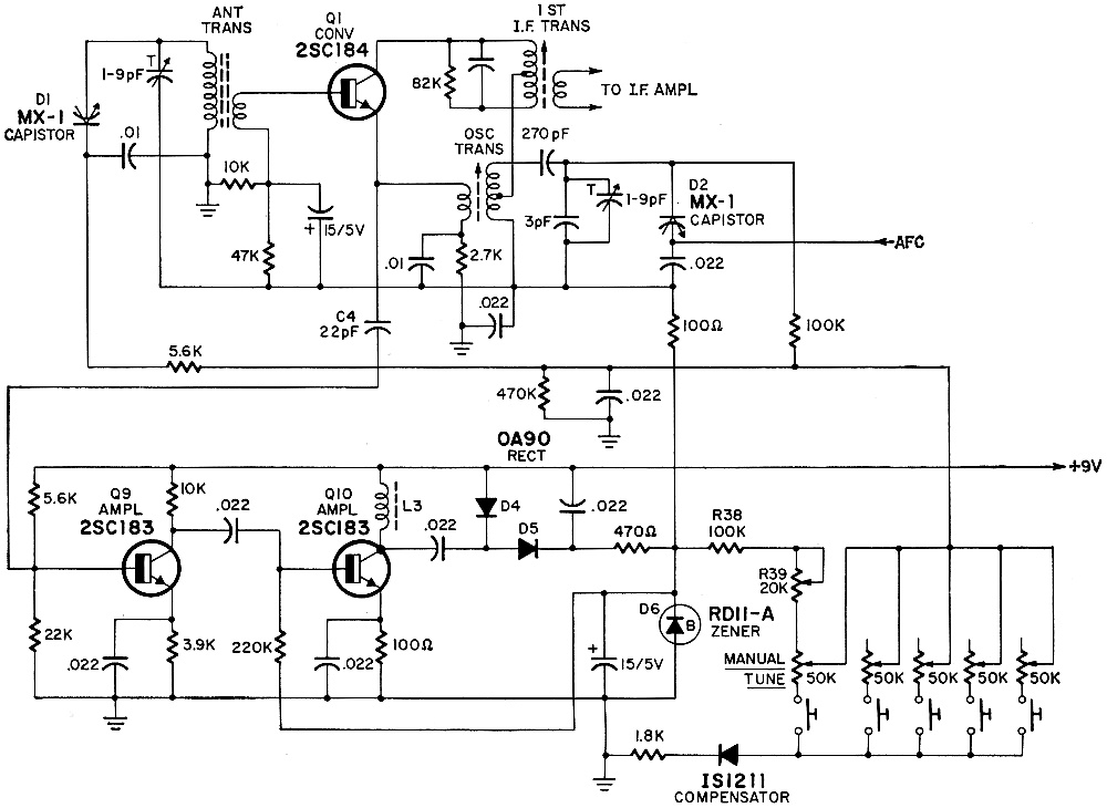
Fig. 6 - Front-end and voltage-regulator circuit in the Panasonic R-J500 battery-powered transistor portable radio. Antenna-tuning diode D1 is fed from the 10-volt bias line through an adjustable voltage divider consisting of R3 and R4, and the oscillator diode is fed from a fixed voltage divider consisting of R1, R2 and R4. R3 is adjusted for proper tracking between the oscillator and antenna circuits. The bias voltage for the tuning diodes is applied through interlocking pushbutton switches S1-S6. When S1 is closed, R5 is used for continuous tuning. Switches S2-S6 and pots R6- R10 are for preset pushbutton tuning. Potentiometer R11 sets the maximum bias voltage developed across the control pots. The BA 163 is supplied in matched sets of 2, 3, 4 or as is required. For any two, the maximum ratio of voltages at 30 pF is 1:1. The basic tracking circuit for any two diodes is shown in Fig. 4. Potentiometers R1 and R2 are set so the capacitance of D1 and D2 is 30 pF. The capacitance ranges that can be obtained by varying voltage Vab (with R1) are 120-260 pF, 30-120 pF and 10-30 pF. When the ratio of the voltages across D1 and D2 is constant, the capacitance differential is less than 5% from 120 to 260 pF, less than 2% in the 30-120-pF range and less than 1 pF between 10 and 30 pF. VVC All-Channel TV Tuner With the coming of varactor-tuned TV tuners, the channel selector can be mounted on any convenient part of the cabinet - or even in a remote location - instead of being mounted directly on the tuner shaft as in capacitor-tuned conventional models. Standard Kollsman Industries has announced a new solid-state all-channel TV tuner whose circuit will probably resemble Fig. 5, which is a basic diagram prepared from US patent No. 3,354,397, issued to Karl H. Wittig and assigned to SKI. In this circuit, VVC's are used for channel selection and for switching between vhf and uhf TV bands. On the vhf channels, antenna coil L1 is tuned by varactor D2. The collector tank circuit of the RF amplifier is composed of L4 tuned by varactor D4. The oscillator voltage is tapped off, amplified, rectified and then added to supply voltage to compensate for low batteries. Oscillator coil L6 is shunted by varactors D5 and D6 connected back-to-back and tied to the tuning bus. (In the oscillator circuit, the RF voltage across the tank coil is high compared to the tuning voltage applied to the varactors. If a single diode were used as in the antenna and mixer tuned circuits, this high RF voltage would lead to frequency instability and high harmonic output. With two varactors back-to-back, the DC tuning bias varies the capacitance of both by the same amount and in the same direction - as with a split-stator capacitor-while the RF voltage causes equal and opposite capacitance changes.) The channel selector consists of a special two-section potentiometer (R2-R3) ganged to band switch S1. As the arm of the channel selector is moved to the right (toward the junction of R2 and R4) the voltage applied to D2, D4, D5 and D6 goes more positive. This decreases their effective capacitance and tunes the antenna, mixer and oscillator circuits to successively higher channels in the vhf band. Coils L2, L3 and L5 are isolated from the circuit during vhf operation by the very low effective capacitance of D1, D3 and D7 which is produced by the negative bias on the switching bus. As the arm of the channel selector passes the mid-point of its travel, it moves to the junction of R3 and R5 and S1 switches to the high position. D1, D3 and D7 are now forward-biased so they act as short circuits or closed switches which connect L2, L3 and L5 in parallel with the vhf coils. This reduces the effective inductance in the antenna, mixer and oscillator circuits so the uhf channels can be covered. Battery Portables Too When VVC tuning was applied to the Panasonic R-1500 battery-powered transistor portable, special circuits were added to insure that a stable 10 volts was available for the Capistors (D1 and D2) in the antenna and mixer circuits so as to compensate for the normal decrease in battery voltage with time and use. The front end and compensating circuits in the R-1500 are in Fig. 6. The set has five pushbuttons: one to select manual tuning and four for pre-set stations. When the set is first turned on, battery current from the 9-volt line flows through D4 and D5 and turns on converter Q1. As Q1 starts oscillating, a part of the oscillator voltage is tapped off the emitter circuit and fed through C4 to the base of Q9. Transistors Q9 and Q10 amplify the oscillator signal and develop a fairly high RF voltage across RF choke L3. This voltage is rectified by D4 and D5 and added to the converter supply voltage and stabilized by Zener diode D6. This stabilized voltage is also fed through R38 and R39 to the manual tuning or preset pots as bias for the Capistors in the antenna and mixer circuits. The afc circuit (not shown) consists of a separate i.f. amplifier stage - fed from the output of the second i.f. amplifier-feeding a discriminator that develops a correction voltage. This voltage is applied to the anode of the oscillator Capistor (D2) to aid or oppose the tuning bias and tune the station in right on the nose.
Posted January 3, 2019 |
|