Understanding Mechanical Filters
|
|
I'm not sure how much mechanical filters are used in circuit design these days due to their somewhat large size and complexity. They typically exhibit a high "Q" with a relatively flat passband (with some ripple) and very sharp cutoff in the skirts, and the insertion loss is low compared to lumped element equivalents (for comparative out-of-band cutoff). Operational frequencies were limited to a few hundred kilohertz, so they are useful only at intermediate and baseband frequencies. This article, appearing in a 1953 issue of Radio-Electronics magazine, describes the basics of mechanical filter design and construction. Mechanical filters from aircraft radio manufacturer Collins and other can be found on eBay. Superior filtering and selectivity is obtainable by use of mechanical filters.
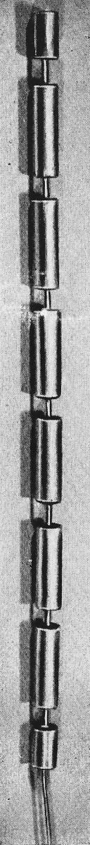
Fig. 7 8-circuit mechanical filter designed for 455 kc with bandwidth of 6 kc. Small necks couple circuits together. By Leslie L. Burns, Jr. Obtaining adequate selectivity is an always-present problem in radio receiver design. Most receivers get the necessary selectivity by cascading a number of i.f. stages. This method does not result in ideal selectivity; it gives us a rounded selectivity curve with broad skirts. The ideal curve would have a flat top and steep sides.
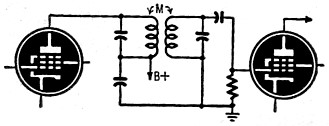
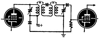
Fig. 1 - Conventional i.f. transformer.
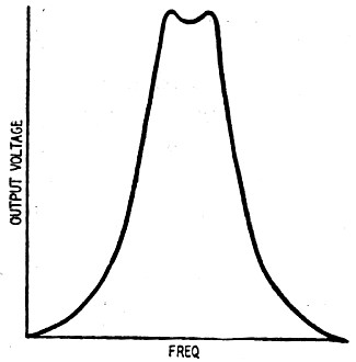
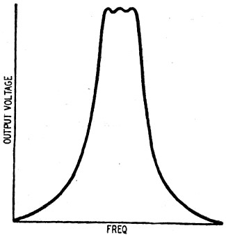
Fig. 2 - Typical response curve for Fig. 1.
Fig. 3 - Coupling with third tuned circuit.
Fig. 4 - Typical response curve for Fig. 3.
Fig. 5 - Mechanical resonator circuit.
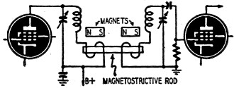
Fig. 6 - Multisection magnetostrictive rod filter. Special commercial receivers for point-to-point communication sometimes use crystal filters of the type used to a great extent in telephone work. These are expensive and not suitable for use in communications receivers for ordinary use. A new answer to this problem is provided by mechanical filters which are becoming increasingly important in radio communications. Several radio sets manufactured for the Armed Forces have mechanical filters. One company markets such a filter for amateur or experimental use and also sells a communications receiver with this filter installed. By a mechanical filter we mean a filter that employs mechanically coupled mechanical resonators as distinguished from one that employs mechanical resonators coupled electrically (as in the case in crystal filters). This definition becomes clearer as a mechanical filter is better understood. These filters make it possible to obtain a lot of filtering in a small space and to maintain the flat top and steep sides so desirable in selectivity considerations. These filters are stable with respect to temperature and humidity. Field maintenance is eliminated, since - once a filter is manufactured - no adjustment is either necessary or possible. Principles of Operation The basic idea behind mechanical filters is very simple and can be easily understood. Consider Fig. 1 which shows a conventional i.f. transformer coupling the plate of one i.f. amplifier to the grid of the next i.f. amplifier. The two tuned circuits are coupled by a mutual inductance. The amount of this mutual coupling determines the bandwidth of this particular transformer. Fig. 2 is a typical response curve for this type of circuit. To obtain more selectivity with this arrangement we might put a third tuned circuit between the two already shown, as illustrated by Fig. 3. Fig. 4 illustrates the response from this arrangement. Now we might continue this procedure until we get a response approaching the ideal, which would be a flat-topped curve with steep sides. These additional electrical circuits would have losses due to the resistance of the coils, and these losses would prevent the selectivity curve from being as steep as might be desired. Also the problem of aligning additional circuits during maintenance operations in the field would be acute. However, these interior electrical circuits can be replaced by permanently tuned mechanical circuits. Fig. 5 shows an arrangement similar to Fig. 3 wherein the middle electrical circuit has been replaced by a single mechanical resonator. This mechanical resonator is exactly equivalent to the middle electrical circuit of Fig. 3, with the additional feature of being of very low loss. Magnetostrictive Conversion The radio-frequency signals must be converted to mechanical vibrations in an intermediate amplifier so that they may be filtered by a mechanical filter. This is done with the help of a phenomenon known as magnetostriction. When certain materials are placed in a magnetic field they expand or contract, depending on the nature of the particular material. Nickel contracts when placed in a magnetic field. Thus a small rod of nickel becomes slightly shorter when magnetized. Now if the magnetic field is made to alternately increase and decrease, the nickel rod will alternately become shorter and longer. If the frequency of the alternating magnetic field coincides with the resonant frequency of the rod, the motion will be relatively large. Efficient electrical-to-mechanical conversion of energy is thus obtained. Conversely, a rod of nickel that is alternately expanding and contracting generates a magnetic field that can produce a voltage in a coil surrounding the rod. In both cases a permanent magnetic field is supplied to prevent double frequency operation. With these two effects in mind it is easy to see that the electrical energy is converted to mechanical energy at the filter input coil by magnetostriction; at the output the reverse phenomenon converts the mechanical energy back into electrical energy. Instead of nickel, most mechanical filters are made of an iron-and-nickel alloy called Ni-span C, which is very stable with respect to temperature.
Fig. 8 - End circuit has narrow diameter.
Fig. 9 - Heavy slugs couple resonators. By continuing the process of adding more mechanical circuits we have the arrangement shown in Fig. 6. Here we have six mechanical circuits and two electrical circuits for a total of eight circuits. This arrangement will provide a selectivity curve with a flat top and steep sides suitable for most communications receivers designed for general use. The bandwidth of this type of arrangement is determined by the relative size of the mechanical resonators to the small coupling necks. The small neck corresponds to weak coupling and produces a narrow band, whereas a larger-diameter neck produces a wider band. To keep the functions of a mechanical filter clearly in mind, imagine each resonator - that is, each large portion of the rod - to be a tuned circuit, and imagine each small neck portion to be like a small amount of mutual coupling. Fig. 7 is an enlarged photograph of an, 8-circuit mechanical filter designed for; 455 kc with a bandwidth of 6 kc. The small necks coupling the mechanical circuits together can be easily seen. The interior resonators of this filter are actually 0.4 inch long. Further Design Considerations The resonant frequency of a magnetostrictive rod is determined by its length. A rod of nickel about 1 inch long will be resonant at 100 kc. The relation is: Length = velocity of sound Length / frequency x 2 The velocity of sound is different in different materials. In nickel it is 1.95 x 105 inches per second, while in Ni-span C the velocity is 1.89 x 105 inches per second. Each of the resonators in a mechanical filter is made exactly this length or some multiple of this length so that they all will be resonant at the center frequency of the pass-band. In some designs the interior resonators are made just twice as long as the end resonators, but they are still resonant at the center of the pass-band. Also, other forms than the rod-shaped resonator can be used in mechanical filters. Disc or spherical resonators can be used. Each of these different shapes has advantages that make it suitable for certain frequencies and bandwidths. The bandwidth of the simple rod-type filter that has been illustrated is determined by the relative size of the coupling neck to the resonator. The relation is: bandwidth/center freq. = area of neck/area of resonator where the area is the cross-sectional area of the neck or resonator. Mechanical filters, like electrical filters, must be terminated for minimum ripple in the pass-band. Termination of a filter for minimum ripple is analogous to terminating a television transmission line for minimum reflections in the picture. Mechanical resistance in the form of mechanical lossy material is attached to the end resonators. (A mechanical lossy material might for example be a small piece of rubber glued to the end resonator.) Another method of producing the required mechanical resistance is to attach a long piece of wire coated with some lossy material to absorb the vibrations. With this method it is easy to get exactly the proper amount of mechanical resistance since the diameter of the wire determines the amount of the losses. Fig. 8 shows the end portion of a mechanical filter with a coiled lossy line attached. Sometimes, when the bandwidth of the filter is not too great, no mechanical resistance in the form of lossy material is necessary, since all the resistance needed to properly terminate the filter is provided by the electrical circuit coupled to the end resonator. Another consideration in mechanical filter design is that, to obtain the flat-test pass-band response, the end resonators must contain half the energy of the interior resonators. This is evident in Fig. 7 where it can be seen that the end resonators are half as long as the others and in Fig. 8 where the end resonator has a smaller diameter than the interior resonators.
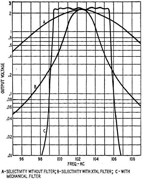
Fig. 10 - Selectivity of various filters.
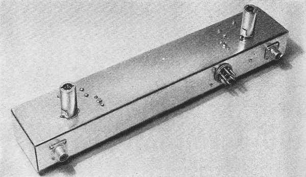
Fig. 11 - A top-side view of a typical mounting for a mechanical filter.
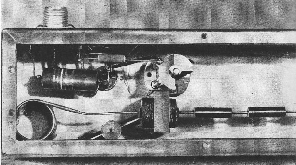
Fig. 12 - The drive coil and permanent magnet can be seen in this bottom view. The circuits of an electrical filter can be coupled by either a mutual capacitance or a mutual inductance. This is true also of the mechanical case. One form of mechanical filter uses heavy slugs to couple the resonators instead of the small necks as has been previously shown. Fig. 9 Illustrates this type of filter. Here the small tubes are the resonators, while the slugs form the couplers. The slugs are about 0.2 inch long, while the interior resonators are about 0.6 inch long. Again on this filter the half-energy end resonators can be seen clearly. A filter of this type is fully equivalent to the other form shown, and the choice between the two is purely a matter of the ease of fabrication for the frequency desired. Applications A typical selectivity curve is illustrated in Fig. 10, which also shows for comparison the curves obtained in a high-quality communications receiver with and without the crystal filter. The crystal filter here referred to is the type usually found in communications receivers and is designed to provide a single sharply peaked response and not a flat-topped response such as is provided by a mechanical filter or a band-pass crystal filter employing several crystals. The electrical circuit diagram for a mechanical filter is given by Fig. 6. A typical mounting for a mechanical filter is illustrated by Figs. 11 and 12 for a 100-kc filter with a 6-kc band-pass. The drive coil and permanent magnet are evident in the under-chassis view. Filters for higher frequencies will have much smaller housings. The application of mechanical filters to high-quality receivers will increase as improved designs and better fabrication techniques are developed. It seems unlikely that they will ever be used in the cheap table-model broadcast receivers because the selectivity of these receivers is now satisfactory. However, the better-quality broadcast receivers will use mechanical filters. The big field for the application of mechanical filters is in communications receivers and in military equipment where the stringent selectivity requirements cannot be met by any other type of filter. References "Compact Electromechanical Filter," R. Adler. Electronics, April, 1947, page 100. "Mechanical Filters for Radio Frequencies," W. van B. Roberts and L. L. Burns, Jr. RCA Review, September, 1949, page 348. "A Bandpass Mechanical Filter for 100 Kc, Leslie L. Burns, Jr. RCA Review, March, 1952, page 34. "Mechanical Bandpass Filters for I.F. Ranges, Ben Roberts, QST, February, 1953. "How to Use Mechanical I.F. Filters," M. L. Doelz and J. C. Hathaway, Electronics. March, 1953, page 138.
Posted November 5, 2020 |
|