Transistor Substitution Box |
|
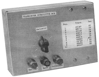
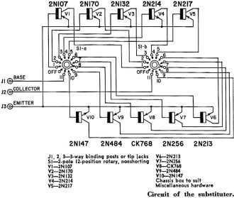
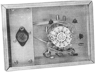
There aren't many people using transistor substitution boxes these days because circuit simulator software is readily available to reasonably predict which type will serve the intended purpose. However, back in 1960 when this article appeared in Radio−Electronics magazine, substitution boxes for not just transistors, but also capacitors, resistors, and sometimes inductors were used quite often when prototyping and/or troubleshooting circuits. I used resistor and capacitor substitution boxes all the time in the early and mid 1980's while working as an electronics technician at Westinghouse Oceanic Division, in Annapolis, Maryland. That was my first place of employment after separating from the USAF. Prior to moving into the engineering lab, I built electronics assemblies for U.S. Navy sonars used on torpedoes, ship hulls, and towed vehicles, including printed circuit assemblies, cable harnesses, chassis assemblies, and piezoelectric transducers. Occasionally, I was tasked to build component substitution boxes for the engineering lab and the test equipment repair / calibration (metrology) group. Little did I know at the time that in the near future I would be using some of the equipment I built. Transistor Substitution Box 10 transistors at your fingertips. Just flip a switch to select the one you want. By Leonard J. D'Airo* This transistor substitution box has proved to be a pretty valuable piece of equipment on a number of occasions when transistor circuits were being checked out. It has taken a rightful place in my workshop, alongside the resistance, capacitance and inductance substitution boxes. A transistor substitution box is, of course, much more expensive than the more usual capacitor or resistor substitute array, at first sight so much so as to appear impractical. But until we get a great deal more familiar with transistor receivers and can spot a bad transistor more easily, the positive answers it gives save enough servicing time to pay for it very quickly. In this unit, there are substitutes for 10 transistors. Included are general-purpose, small-signal audio, large-signal audio, power and RF types. Selection is for useful characteristics and any combination may be used. The combination shown in the schematic covers most practical applications. These transistors are: General purpose 2N107, 2N170 Note that in the first three groups, one transistor is a p-n-p and the other is an n-p-n, while the power transistor is a p-n-p (since most applications use a p-n-p unit). In the RF group, two transistors are p-n-p's and one is an n-p-n. Inside the substitution box. Author used transistors other than those in the schematic and listed on the box's front panel to match his own special requirements. The transistors suggested in the parts list represent the average units used in transistor radios, amplifiers and related equipment. The types that are finally chosen and used should match the particular requirements of the user. A cigar box or aluminum chassis box can be used to mount the selector switch and transistors. All wiring must be quite rigid and as short as possible. The power transistor must be mounted on a heat sink and kept as far as possible from other transistors. * Author Servicing Transistor Radios, Gernsback Library.
Posted February 23, 2023 |
|


