ABC's of Transistors |
|
Sylvania was yet another bedrock American technology innovation company that in the last few decades has been bought by foreign concerns*, while retaining at least some semblance of its original identity - mostly for brand loyalty purposes. Along with pioneering lighting products, Sylvania produced vacuum tubes and semiconductors for use in its line of radios and televisions. Sylvania engineers published a lot of articles in electronics magazines introducing transistors and early integrated circuits to laymen, hobbyists, and professionals, some of whom were fledglings to the field and others who were transitioning tubes types. This particular article suggests methods for verifying operation of PNP and NPN bipolar junction transistors (BJTs) and for troubleshooting basic circuits. See also "ABC's of Transistors - Here's How They Work." * Bought by Germany's OSRAM in the 1990s and then by China's LEDVANCE in the 2010s. ABC's of Transistors by Sylvania Technical Staff
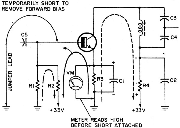
Fig. 1 - Typical transistor circuit with voltmeter checkpoints.
Fig. 2 - Jumper wire removes forward bias.
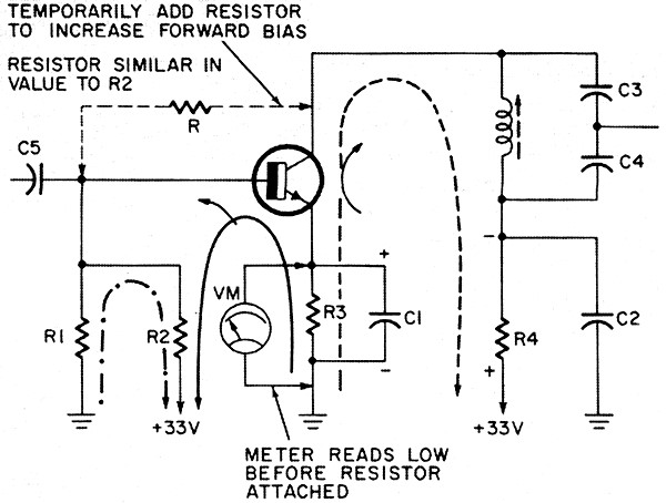
Fig. 3 - Increasing the forward bias temporarily.
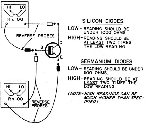
Fig. 4 - Checking check each of the two diode junctions in a transistor.
Fig. 5 - Checking forward bias on pnp transistors.
Fig. 6 - Collector will vary as a function of base voltage and input signal.
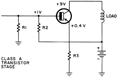
Fig. 7a - Class A amplifier stage.
Fig. 7b - Class C oscillator. Defects in transistor circuits can be localized by measuring the voltage on the transistor terminals, since the defective component often upsets the current drawn by the stage. The change from normal causes a different voltage to develop across the resistive components in the circuit. A typical transistor circuit with voltmeter checkpoints is shown in Fig. 1. The emitter resistor is common to both the input and output circuits, so voltage drop Vm, across the resistor, is a result of the total transistor base and collector current. This voltage drop is a good indicator of transistor current. Collector current can be determined by simply measuring the voltage drop across decoupling resistor R4 and using Ohm's law. If the voltage across the emitter resistor, R3, is off, we then want to know if the transistor can control current. If we determine that the transistor base is not capable of control, we can assume the transistor is defective. If we find the base is capable of current control, we would then assume that the stage is biased incorrectly, indicating a defective bias resistor or other component such as a shorted coupling capacitor. One way of determining if the transistor base is capable of controlling the current is by temporarily adding to or subtracting from the bias voltage and noting if there is a corresponding change in voltage drop across emitter resistor R3 or decoupling resistor R4 (see Fig. 2). Suppose the emitter voltage is higher than normal. Since the current must be high, we temporarily remove the forward bias from the stage and determine if this will reduce the voltage drop across R3. One common way of removing forward bias is to short the base and emitter together using a small screwdriver. This may not, however, always give a clear indication of current control. A more certain way is to use a short piece of jumper wire to connect the base back to the same source potential as the emitter, which in (Fig. 2) is ground. This positively removes any forward bias. If, after the forward bias is removed, as indicated the drop across the emitter resistor does not fall to a low value, the base element is not able to control the current and the transistor is probably defective. If the voltage drop across the emitter resistor does fall to a very low value, the base can control current, the transistor is probably good. If measuring the emitter voltage discloses an abnormally low reading, try increasing the forward bias temporarily to determine if the base element can control the current (see Fig. 3). Temporarily connect the base to the collector through a series resistor R similar in value to bias resistor R2. Obviously, first make sure that collector voltage is present. If the transistor base element has control of the current, connecting the resistor as shown should increase the voltage drop across resistor R3. This indicates that the transistor is probably good and a biasing defect such as R1, R2, or a shorted C5 is indicated. If attaching the resistor as indicated does not increase the current, the transistor is open. The procedure can be simplified for most transistor in-circuit testing by the following procedure. Measure collector voltage. If it is lower than the supply voltage, the transistor is conducting. With the meter still on the collector, short the base to the emitter. If collector voltage rises to the supply voltage, the transistor is not shorted and can be turned off. This simplified procedure will not always work; i.e., a collector connected to ground. But as experience in servicing transistor circuits is gained, it becomes easier to see where this technique is applicable and it certainly is a fast, simple way to evaluate a transistor without removing it. Once you are sure the transistor cannot control current, it is usually advisable to remove the transistor. This will allow you to measure the bias resistor values without the inaccuracies of having the transistor junctions across them. Every effort should be made to determine that a particular stage does contain a defect before removing the transistor. If a transistor appears to be open by the above checks, before removing it from the circuit, check it as follows. In-Circuit Diode Checks Use an ohmmeter on its R times 100 scale to check each of the two diodes in a transistor (Fig. 4). To check the collector diode, connect one lead to the base and the other to the collector and note the reading. Reverse the leads and note the second reading. The lowest reading should be under 500 ohms for germanium transistors and under 1000 ohms for silicon transistors. The high readings should be at least two times the low reading. Perform the same test on the emitter diode to check the transistor completely. Make these checks with power removed from the circuit. Detector and age diodes can be checked in the same manner. Transistor Operating Class C In a class C stage where collector current flows for relatively short intervals of time, DC voltage measurements on the transistor differ from those in a class A stage. Check forward bias on pnp transistors by connecting the positive voltmeter lead to the emitter and the negative lead to the base (see Fig. 5). Read the bias indication directly on the meter. Measuring the emitter and base voltages to ground, and subtracting them, is not reliable or accurate. The collector will vary as a function of base voltage and input signal (see Fig. 6). The input signal has the same magnitude in all three cases. When the base voltage is 0.65 volt, the input signal adds to and subtracts from the base voltage and we get a linear output. This is class A operation and the average collector current is a constant value. When base voltage is 0.5 volt, only the positive-going half cycle of the input signal effectively adds to the base voltage, causing an increase in collector current. The negative portion of the input signal drives the transistor into cutoff. This can be likened to class B operation where collector current flows for only one-half the cycle. When base voltage is 0.4 volt, the transistor is in cutoff and no collector current flows. Only the most positive portion of the input signal causes collector current which is in pulses representing the positive peaks of the input signal. A class C stage is usually biased into cutoff so no collector current flows until the input signal turns the stage on. It becomes apparent that the amount of base to emitter voltage or forward bias measured on a stage will depend upon whether the stage is operating class A, B or C. To demonstrate how voltages will vary from a class A stage to a class C stage, we can make the class A amplifier into an oscillator as shown in Fig. 7. The usual forward bias will not be found on converter and oscillator transistors since bias varies with frequency of oscillation. The emitter and base voltages of oscillators and converters are shown nearly equal on the schematics, although they do vary somewhat. If a radio converter has a steady 0.2-volt bias when it is tuned, the oscillator is probably not functioning. That's it on transistor stage checking. Next time we'll take a detailed look at transistor tests and circuit applications.
Posted June 5, 2019 |
|