Fundamentals of Radio Servicing: Part XXIII - Signals in Space
|
|
John T. Frye, creator of the Mac's Radio Service Shop and Carl & Jerry technodrama™ article series, employed his mastery of electronics to weave into tales valuable lessons in circuit design and troubleshooting, business practices, dealing with customers, test equipment usage, education, as well as introducing new technology. His columns ran for decades in multiple electronics trade and hobby magazines (see the huge lists at the bottoms of the two pages liked above). In addition to that, Mr. Frye wrote many technical articles such as this "Fundamentals of Radio Servicing" piece that ran in a 1951 issue of Radio-Electronics magazine. It is Part 23 of a series and deals with "Signals in Space." An avid Ham operator, he is aware that it was radio amateurs who played a large role in early discoveries concerning how electromagnetic waves are affected by ionized layers in the Earth's upper atmosphere. Fundamentals of Radio Servicing: Part XXIII - Signals in Space
In the last chapter we wrote as though the transmitted radio wave traveled a simple, straightforward path from transmitting antenna to the various receiving antennas. That is not the case! Nothing about this wacky radio business could ever be that simple, direct, and easy to understand!
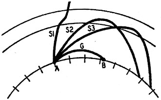
Fig. 1 - How radio waves act in space.
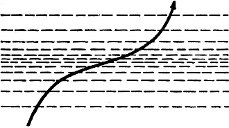
Fig. 2 - Wave path in an ionized layer.
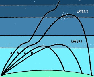
Fig. 3 - The amount of bending depends on the angle at which the wave strikes.
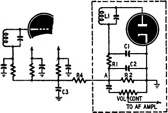
Fig. 4 - A detector circuit with a.v.c.
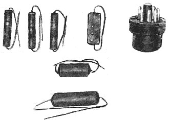
The components for an a.v.c. circuit. Fig. 1 shows what really happens. Some of the waves from the transmitter at A travel along the surface of the earth like the one designated G. These "ground waves" induce currents in the earth immediately beneath them, and the resistance of the earth to the passage of these currents cause them to die out rapidly, particularly at the higher frequencies. On the broadcast band these ground-hugging waves account for practically all the daytime reception. They are good for about 50 miles at the high-frequency end of the band and up to 200 miles at the low-frequency end. Then there are the "sky waves" that travel upward from the transmitter at various angles as shown at S1, S2, and S3. Some of these waves, like the one at S1 , imitate the famed traveling salesman and keep right on traveling, never to be heard from again. Others, like S2 and S3, meet a "something" up there in the wild blue yonder that persuades them to turn around and come back to earth. The "something" that turns them back is a series of ionized layers above the earth's surface at various distances of from 30 to 250 miles. You will recall that an ion is really a positively charged molecule that got that way from having lost some of its negative charge in a collision with a fast-moving electron or through some other molecular mayhem. The gases in the upper reaches of the earth's atmosphere are being constantly bombarded by ultra-violet and cosmic ray radiation, and this bombardment ionizes many of their molecules. Since these gases hover at various heights according to their weight, and since the bombardment is more effective as the atmosphere becomes rarer, it is not surprising that the ionization is in layers, each layer being more intensely ionized than the one below it. Did you ever see a stick lying half in and half out of a pool of clear water and notice that the stick seemed to be sharply bent right at the point where it enters the water? We learned in high school physics, of course, that it was not the stick but the light rays reflected from it that were bent. Just as a light ray changes course when it passes from one medium to another, so are radio waves bent when they pass through an intensely ionized layer. The wave behaves as though it hated ions and wants to avoid any concentration of them. This is shown in Fig. 2. Notice that as the radio wave enters the ionized layer from below, it tries to shy away from the more deeply ionized center portion of the layer; but once it is forced to pass through this center portion, it reverses its direction of curvature so as to escape from the layer as soon as possible. The actual amount of bending depends upon three things: the angle with which the radio wave strikes the layer, the frequency of the wave, and the intensity of ionization of the layer. If the wave strikes the layer nearly at right angles, as shown at A in Fig. 3, there is very little bending. As this angle decreases, the bending becomes more pronounced, as illustrated at C and D. A low-frequency wave bends or "refracts" much more than one of higher frequency. If a wave of a given frequency strikes the layer at an angle that just permits it to be bent back to earth, one of a little higher frequency will pass on through the layer. Often a wave will penetrate a lower layer only to be turned back by the increased ionization of the layer above it, as pictured at B. The whole subject of what happens to a radio wave in the ionosphere is a most interesting and complicated one, but we do not need an exhaustive explanation of the various phases of that esoteric matter. For our purposes we need know only that sky waves can be bent back to the earth in the ionosphere; that most broadcast-frequency sky waves are absorbed in this region during the day time but are returned to earth at night; and that the exact spot to which a wave returns depends upon several highly variable factors. And now we are ready to take up fading. As the curtain rises on this drama, we see two portions of the same radio wave perched on the transmitting antenna just prior to taking off. The ground wave is saying to the sky wave, "You take the high road and I'll take the low road, and I'll be there before you." It is this choice of paths by 'which the signal can go from the transmitter to the receiving location that causes the trouble. If the receiver is near the transmitter, reception is dominated by the powerful ground wave and is not affected by any sky waves that mayor may not be returned from the ionosphere. As the distances from the transmitter increases, the ground wave grows weaker and weaker until finally it cannot be heard at all. At this point and beyond, the station cannot be received in the daytime. At night the waves "reflected" from the ionized layers permit signals to be received. At a point where the sky wave and the ground wave are received about equally well, we have an area or belt of very bad "fading," or fluctuation in the intensity of the received signal. Since the two portions of the same signal arrive over different paths and cover different distances, they may arrive with a difference in timing or "phasing" that will cause their two separate intensities either to be added together or to buck one another. In the first case, the resulting signal will be stronger than the one from the ground wave alone; in the latter the two portions may so effectively cancel one another that nothing can be heard. Furthermore, since the path the sky wave travels is constantly changing with shifts in the height and ionization of the refracting layer, the signal intensity may vary constantly between these two extremes. You might think that once the receiving station was beyond the reach of the ground wave, fading would be at an end, but such is not always the case. You have to remember that the wave-bending ionosphere is as unstable as a bucket of smoke and the path pursued by a radio wave through this ionosphere is constantly changing. At one time the receiver may be getting the full intensity of the refracted wave, while a few minutes later this center of intensity may have shifted to a spot several hundred miles away, and the receiver will be sitting in the weak fringe of the earth-returning wave. What is even worse, the sideband frequencies of the wave may travel different paths in the ionosphere because of their slightly different frequency, and when they arrive at the receiver the phase of these intelligence-carrying sidebands may be altogether different from what they were at the transmitter. As a result, the music or voice may be very badly garbled by the interaction of these out-of-phase side-bands. This very annoying brand of fading accompanied by distortion is called "selective fading." Night radio reception in the old days used to be a pretty exasperating affair. The operator had to ride the controls constantly to prevent the received signal from blasting the speaker one minute or fading clear out the next. The cure, once found, was simple. Automatic volume control was the very poor name selected for it. I say "poor" because it is evident that any attempt to hold the volume at a constant level - making the whisper of the flute as loud as the bellow of the tuba - would result in distortion. What really was done was to make the r.f. sensitivity of the receiver inversely proportional to the intensity of the signal. As the signal intensity goes up, the receiver sensitivity goes down, and vice versa. The end result is that the signal delivered to the detector is practically independent of variations in the strength of the received signal. This control is secured by varying the bias voltage applied to the r.f., mixer, and i.f. stages. As the negative bias on the grids of these tubes is increased, their ability to amplify is decreased, and the sensitivity of the receiver is reduced. Since we want this bias voltage to rise and fall with the strength of the received signal, the best place to get such a control voltage is from the signal itself. The d.c. voltage drop across R2 is produced by rectifying the carrier envelope; so it stands to reason that it will be directly proportional to the amplitude of the carrier. If this amplitude increases, point A will become more negative with respect to ground; if it decreases - which is another way of saying the intensity of the signal goes down - point A becomes less negative. Before this controlling voltage can be applied to the grids of our r.f. and i.f. tubes, however, we must comb out of it the a.f. variations still present at point A. This is done by means of a resistor-capacitor filter R4-C3. The values of this resistor and capacitor are carefully chosen and should not be changed. When a capacitor charges and discharges through a resistor, as happens here, the time required for the voltage to build up and fall depends upon the values of the two components. The larger they are, the more time is required. What we want here is a combination that will be too slow to follow the voltage variations caused by the lowest audio frequency but fast enough to let the system have time to "recover" in the time required to tune from one station to another. Otherwise, when tuning from a strong station past a weak one, the sensitivity of the receiver might not have time to adjust itself upward after leaving the strong station, and the weak station would not be heard. The usual time constant is 0.1 second. This negative voltage is fed to the various grids of the controlled tubes through isolating resistors that prevent coupling between the grid circuits. Tubes controlled by a.v.c. are the "remote-cutoff" type, the ones whose amplifying properties respond smoothly to wide variations in bias voltage. These tubes also are provided with a certain amount of minimum fixed bias - such as cathode bias - so that the plate current does not become excessive when no a.v.c. voltage is being produced.
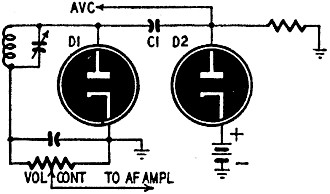
Fig. 5 - A basic delayed a.v.c. circuit. In an ordinary a.v.c. system, the controlling action starts on even the weakest signal and begins to reduce the gain of the receiver when increased sensitivity would really be a help. "Delayed a.v.c.," as diagrammed in Fig. 5, shows the basic circuit for overcoming this problem. One diode D1 of a duo-diode is used for detection in the usual manner. The i.f. signal is also applied, through C1, to D2. The cathode of D2 is positive with respect to ground, which makes the plate negative with respect to the cathode. As long as the peak amplitude of the i.f. signal applied to D2 is less than this bias voltage, there will be no rectification, and consequently no a.v.c. voltage will be developed. As soon as the peak i.f. voltage rises above this bias voltage, rectification begins and the a.v.c. voltage is developed just as before. A battery is used for bias in the diagram, but the cathode may be tapped in at some point on a current-carrying resistor to get the correct bias. Automatic volume control troubles are almost entirely due to failures of the capacitors, resistors, or diodes that make up a.v.c. circuits. Since the voltages are fed to the grids of the tubes through high-ohmage resistors, even a slightly leaky capacitor will short-circuit the a.v.c. voltage. A possibly worse trouble is an intermittently leaky capacitor, which will produce its own type of fading. Where the complaint is "fading" or "intermittent," it is often a good idea to replace all capacitors in the a.v.c. circuit and to replace or make sure the resistors are not changing their ohmage.
Posted January 8, 2021 |
|

 By John T. Frye