Missile Control and Guidance |
|
It is no stretch of the truth to say a sub-$100 remote-controlled drone or airplane from the toy aisle in Walmart today has more sophisticated guidance and stability control than the most advanced missile available in 1960, when this "Missile Control and Guidance" article appeared in Radio−Electronics magazine. Multi-axis accelerometers, processors, motor controllers, and even wireless off-vehicle communications are integrated into a couple (or a few, depending on the capabilities of the platform) integrated circuits. A full-color camera, possibly on a controllable gimbal, might be part of the system. True, scaling vehicle control mechanisms up to handle the rugged environment of a real-world missile with critical propulsion, flight, targeting and detonation mission requirements requires much more engineering than a toy aircraft. My point is that the heart of the system in 1960 was more crude and less capable than today's recreational vehicles. It is akin to how your smartphone has more computing and data storage capability than a 1960's era mainframe computer - and significantly more than the Apollo 11 flight control computer that delivered three men to and from the moon for the first time in July of 1969. Missile Control and Guidance
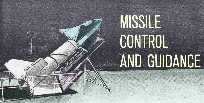
Missile on target! Sounds simple, but it takes a complicated guidance system to make it true. Marvin Hobbs* Missiles take the form of either aircraft flying within the earth's atmosphere or rockets propelled within or outside the earth's atmosphere. Turbo - or ram-jet aircraft operating as missiles, are stabilized and guided by adjusting the position of the flight-control surfaces-rudder, elevator and ailerons. The three motions of a missile which the flight surfaces can affect are known as roll (when one wing becomes alternately higher and lower than the other), pitch (alternate nose-up, nose-down oscillations) and yaw (deviation to right and left of correct compass course (Fig. 1). In addition, the direction of the propelling thrust may be varied to change the course of rocket-driven missiles. This method is particularly applicable when rocket-powered missiles are traveling outside of the earth's atmosphere.
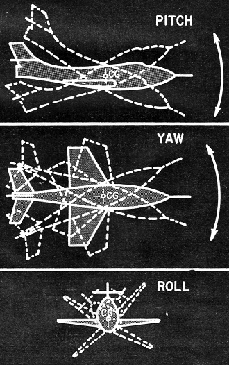
Fig. 1 - Pitch, yaw and roll occur in missiles and aircraft. All movements are around the center of gravity (CG). The direction-controlling elements of a missile are usually moved by either fluid-driven or air-driven piston-like devices. In a typical hydraulic system, oil is the fluid and is brought to the required pressure by a hydraulic pump. A valve whose position is controlled by the amplified output of the guidance channel determines the direction and amount of fluid flow. This driving medium adjusts the position of the actuator piston, which is linked to and regulates the movement of the control element - whether it be the thrust control of a rocket or the rudder (or other (control surface) of a jet aircraft (Fig. 2). Because of the high speeds of most missiles, the actuators must respond very rapidly to any corrective impulses as required. The guidance signals must be amplified sufficiently to insure positive servo-valve operation ahead of the actuators. Stability Control The surface and thrust controls of pilotless aircraft and rockets must provide for flight stability as well as guidance. In other words, the missile can be guided into the desired trajectory only if it is in stable flight, not wobbling on and off course. Before considering guidance-signal sources, let us examine the key component for achieving flight stabilization, the gyroscope. Since the early 1900's, engineers have been using the gyroscope to stabilize and direct the motion of torpedoes, ships and aircraft. Without the gyroscope, modern guided missiles would not exist in their present form, if at all. Gyroscopes placed about the missile flight axes can help furnish signals to restore the missile to stable flight in its original direction. Two basic characteristics of the gyroscope make it a very important tool in missile stabilization and guidance. One is its axial rigidity in space; the other is its tendency to precess when subjected to external forces. When a gyro rotor is brought up to speed and aligned in a given direction in space, it can be used as a flight-axis reference for an aircraft or missile. By "picking signals" off the gimbals in which the rotor is mounted and amplifying and passing them through appropriate servo and actuator arrangements, the flight control surfaces can be moved to restore the missile to its desired course. Another important consideration, the rate at which the missile is deviating from its course, can be measured by the precession of a rate gyro and also fed into the control system. A typical combination of a position gyro and a rate gyro to control the roll of a missile is shown in Fig. 3. Combinations of gyroscopes to provide flight stability around the three axes of flight motion have been known for some time as "autopilots."
Fig. 2 - Control surface (elevator) is moved by hydraulic actuator which in turn is controlled by spool valve.
Fig. 3 - Position and rate gyros can provide signals for missile control.
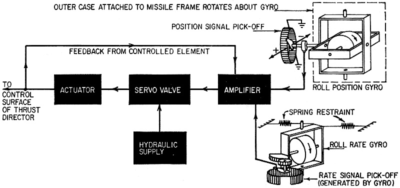
Fig. 4 - Main elements of missile control-and-guidance system. Guidance Such autopilots can give the missile flight stability, but guidance signals must be fed from radio, radar, accelerometer, programmed or additional gyroscopic sources to bring the missile into a desired flight path. Guidance systems vary somewhat, depending upon whether moving or fixed targets are being attacked. Typical moving targets are enemy aircraft, ships or tanks in motion. Fixed targets are cities, industrial centers and military installations. A moving target presents a special problem. Information relative to its position, velocity and direction must be obtained and used to guide the missile to it. The faster the target moves the greater is the problem of catching it with an attacking missile. If several targets are to be intercepted at any given time, the problem becomes even more complex. A missile may strike close enough to a fixed target (with an atomic warhead) if it is simply aimed at the correct angle and given the necessary velocity. Just as with guns firing at moving targets, it is necessary to use a computer to determine the angle at which the missile should be aimed. Calculations must take into account the speed of the target and the factors affecting the missile's direction and time of flight. Whether inside the missile or outside, the computer is part of the automatic system (Fig. 4). In general, wherever a comparison must be made between the missile's position and the course which it should follow to intercept its target, a computer is a necessary system element. Both analog and digital computers are used in a wide variety of missile applications. The allowable weight and volume of the computer vs the required accuracy are determining factors in the choice of type. Passive Systems The simplest type of guidance system - and probably the most foolproof one - can be realized in attacking targets which radiate some form of energy can sense. Such radiation might be sound, light or heat. If the target radiates enough energy, the guidance may be completely passive, using only a receiver of the radiation. As far as is known, no modern missile operates on sound or light radiated from the target, but excellent ones have been developed to home on the heat of aircraft engines (or other targets). Examples are the US Sidewinder and the British Firestreak which home on infrared energy.1
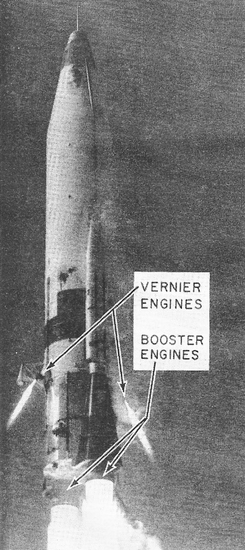
An Air-Force Atlas InterContinental Ballistic Missile (ICBM) thunders aloft from its launching pad at Cape Canaveral, Florida.
Fig. 5 - Typical command guidance system. Signals may he transmitted to missile via uhf-radio link or along the missile-tracking radar.
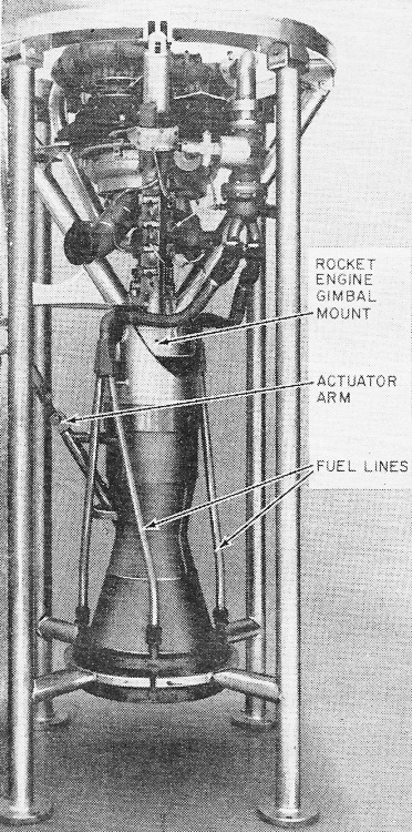
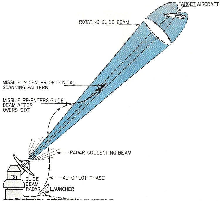
Liquid-fuel rocket engine in gimbal mount. Martin Co. Another type of passive guidance uses inertial navigation principles and has been applied successfully to ballistic missiles.2 Active and Semi-Active Guidance Any guidance system which requires the radiation of energy, either from the missile or another source, to select and track the target is an active or semi-active type. If the target-tracking signal is radiated from the missile, the guidance is active, if it is radiated from a source outside of the missile the guidance is said to be semi-active. Semi-active guidance is most widely used by defensive missiles which, before they are launched, preferably track incoming aircraft from a surface point, such as from the ground or from a ship. Command guidance, beam-riding and semi-active homing are in this category. The basic concept of command guidance is this: Directing or commanding signals are sent to the missile from a control point instructing it as to the course it must take to intercept the target. In one rather well known form one ground radar system tracks the aircraft and another tracks the missile. Taking into account the speed and direction of both target and missile, a ground-based computer determines the corrections in the missile's course to intercept the target. Commands can be sent to the missile over a separate radio channel or are modulated onto the missile-tracking radar and sent to the missile by that route. Certain versions of the Nike missile, designed to intercept high-flying aircraft over major populated or critical defense areas, are guided by a radar command system (Fig. 5). Beam-riding guidance is another variation of the active technique. A single radar beam tracks the target and the missile travels up this beam to intercept it. As some have said, it makes the radar beam lethal. After a beam-riding missile is launched, its first flight phase is controlled by its autopilot. Then it travels through a so-called collecting beam radiated from the ground radar and is brought under ground control. From this phase, its receiver picks up signals from the central guidance beam and it follows this narrow cone of radiated energy to the target. Actually, the ground (or shipboard) radar sweeps out a conical beam around the target. Radar-beam modulation permits the missile's receiver to identify deviations of its course from the center of the conical scan. Signals developed within the missile as a result of any "off-course" modulation are fed to a computer which determines the corrections necessary to intercept the target (Fig. 6). Homing Methods Both command and beam-riding guidance are semi-active systems. However, they are usually not specifically identified in this fashion. In another guidance method-homing (passive homing involving infrared seekers has already been mentioned), it is necessary to qualify the particular system as either active or semi-active. In active homing the missile carries the entire guidance system within itself. But, in semi-active homing, separate radar equipment tracks the target and is said to "illuminate" it and provide a reflected signal for the missile. Since a complete radar system (transmitter and receiver) involves a substantial amount of equipment (even for short operational ranges), active homing has not been popular. Semi-active homing keeps equipment in the missile to a minimum just as in passive homing .. Only the receiver and tracking antenna are required. It is an accepted guidance system for certain modern defense missiles. The British Bloodhound, a semi-active homing missile, is one of the most widely used missiles produced outside of the USA. Made in England, it is used for defense against jet bombers by England, Sweden and Australia. In operation, combined or separate early-warning and tactical-control radar pick up the target aircraft at some distance from the defense point. As the target approaches, a "target-illuminating" radar takes over the tracking and "illuminates" the incoming aircraft (Fig. 7). Prior to missile launching, it provides accurate target position data to the launchers, so that the missile is pointed toward the target before launching. After launching, the missile's receiver extracts yaw and pitch information from the reflected radar signal so that its antenna can be pointed at the target (and the missile's wings moved to steer it into an interception course). In the US, the Army missile known as the Hawk also depends upon semi-active homing. Its name is derived from "Homing All the Way Killer." Its principal application is stated to be against high-speed, low-flying aircraft. Ballistic missile control The rocket exhaust of a long-range ballistic missile soon propels it beyond the earth's atmosphere, so that wings and aerodynamic surfaces are of little value in controlling its flight path. The only practical means of exercising control (and guidance) is by controlling the direction of the rocket engine's thrust. One system moves vanes in and out of the exhaust. Another moves a deflector ring - known as a "jetavator" - across the thrust stream. However, a more widely used technique for large missiles, such as ICBM's and IRBM's uses one or more gimbaled engines. In this design, the entire combustion chamber of the rocket engine (with its exhaust nozzle) is moved in a gimbal mount to give the desired thrust direction. Small auxiliary thrust directors, called vernier engines, usually supplement the main rocket engines. They are quite effective in controlling the roll of the missile as well as furnishing limited pitch and yaw corrections. Ballistic missiles present a special problem when it comes to guidance - the target is not contacted by either self-generated or reflected radiation. Its position is established by geographic coordinates, and the missile's behavior is similar to that of a long range artillery shell. The principal difference is that the ballistic missile can be guided over a somewhat greater portion of its flight path than the shell. After the shell leaves the gun barrel, it receives no further guidance. However, the ballistic missile can be guided as long as there is enough fuel to power the rocket engines.
Fig. 6 - In a beam-riding system, the missile follows the radar beam right up to the target.
Fig. 7 - Missile follows (homes on) reflected radar signal from target.
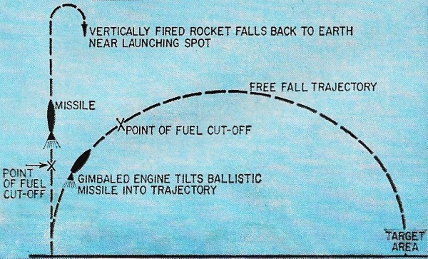
Fig. 8 - Ballistic missile follows free-fall trajectory after point of fuel cutoff. As mentioned above, long-range missiles are well beyond the earth's atmosphere (effectively) before their fuel is cut off and they begin their free fall to the target. By analogy, the guidance system for a ballistic missile establishes a hypothetical "gun-barrel" in space, which for long-range missiles, extends several hundred miles from the launching site. The ballistic path If a rocket is stabilized and launched in a vertical position, it will rise perpendicular to the earth's surface and fall back to a point near the launching site. It could be stabilized with an auto-pilot. However, rockets with vertical trajectories are primarily for research purposes. Missiles must travel some distance from their launching site if they are to operate as military weapons. The missile must be tilted from the vertical position after it is launched. One of the first practical applications of ballistic missiles was the historic German V-2. It was launched vertically and stabilized with an autopilot (consisting of gyroscopes to sense yaw, pitch and roll deviations). But, one of the gyroscopes was precessed in accordance with a timed program to tilt the missile along the pitch axis. Because it was tilted to the proper angle, the V-2 traveled approximately 200 miles from its launching site. However, in addition to establishing the correct pitch angle of the ballistic missile, it is important to cut off the rocket thrust when an exact velocity is attained to insure a desired range. The range of a ballistic missile is determined by its direction and speed at the point of thrust cutoff. To determine the fuel cutoff point, it is necessary to measure the velocity at which the missile is traveling in its flight path. One method for doing this uses the Doppler effect. A small transponder in the missile can indicate the Doppler frequency shift to a ground station, from which a command signal can be sent to cut off the fuel at the desired missile velocity. In another method, an integrating accelerometer measures the missile's velocity and establishes the correct point for shutting off the rocket engine. To be accurate, a ballistic missile must also be on course from a lateral or yaw viewpoint. Modern missiles employ combinations of radar and inertial guidance or inertial guidance alone to establish correct pitch and yaw angles as well as the correct point for thrust cutoff.2 A system using both radar and inertial techniques is known as radio-inertial guidance. The radar portion of the system operates like a command guidance type from ground to missile and adds computed corrections to supplement the accelerometer signals of the inertial portion. The goal of inertial-guidance designers - to obtain sufficiently accurate information from the accelerometers, without radar tracking - has been realized for some systems. Bibliography 1 James R. Spencer, "Infrared Guides Missiles," Radio-Electronics, January, 1960. 2 Philip Julian, "Inertial Guidance Directs Planes and Missiles," Radio-Electronics, December, 1958. * Author: Basics of Missile Guidance and Space Techniques (John F. Rider, Publisher, Inc.)
Posted March 10, 2023 |
|