Microwaves Part V - Waveguide |
|
Although the subtitle of Part V of the 1949 Radio−Electronics magazine "Microwaves" introductory series in refers to Special Sections of Waveguide Are Employed as Transformers, author Palmer is discussing not impedance transformers but physical configuration transformations. That includes in-between rectangular, circular, and oval cross-sections, in-between waveguide and coaxial cable, and rotary joints. Signal injection and extraction via stubs are also covered. He provides a high level introductory description of how microwave frequency waveguide works without delving into the scary mathematics required to design the components. Microwave Series -- Part 1: How Radio Waves Can Be Transmitted Inside Pieces of Pipe (4/49), Part II: An Introduction to Standing Waves, Cavity Resonators, and Representative Examples of u.h.f. Plumbing (5/49), Part III: Tubes for the Microwave Frequencies, Giving Special Notice to the Lighthouse Triode, Velocity-Modulated Tubes, and the Magnetron (6/49), Part IV: How Waveguides Are Joined and Tuned for Lowest Possible Loss (8/49), Part V: Special Sections of Waveguide Are Employed as Transformers (9/49), Part VI: Some Equipment Used for Measuring Frequency, and Crystals for Receiver Frequency Conversion (10/49), Part VII: Action of Below-Cutoff Attenuators and of TR and Anti-TR Switches (11/49), Part VIII: Receiving and transmitting antennas for microwave communication. Special Sections of Waveguide Are Employed as Transformers
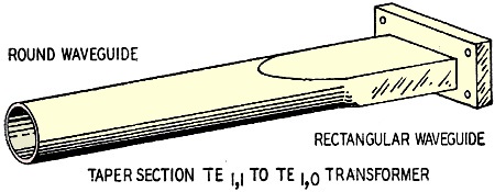
Fig. 1 - Taper section changes shape of guide. Part V - Special sections of waveguide are employed as transformers By C. W. Palmer In addition to the impedance transformers used in microwave installations mentioned in a previous installment of the Microwave series (which usually take the form of cavity resonators) there are also transformers which permit changes from one type of waveguide to another; one mode to another; from waveguide to co-axial line. One example is in changing from the lowest mode of one size guide to the lowest mode of another as between the TE1,0 mode in rectangular waveguide to the TE1,1 mode in circular guide. It is usually advantageous to use the lowest mode of a waveguide which explains why so much of our discussion is based on the TE1,0 mode in rectangular guide. (An exception to this rule is in the use of rotary joints to permit rotating an antenna through 360 degrees or through a desired wide angle.)
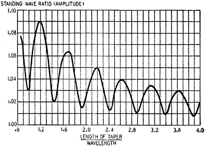
Fig. 2 - Length of taper determines the s.w.r.
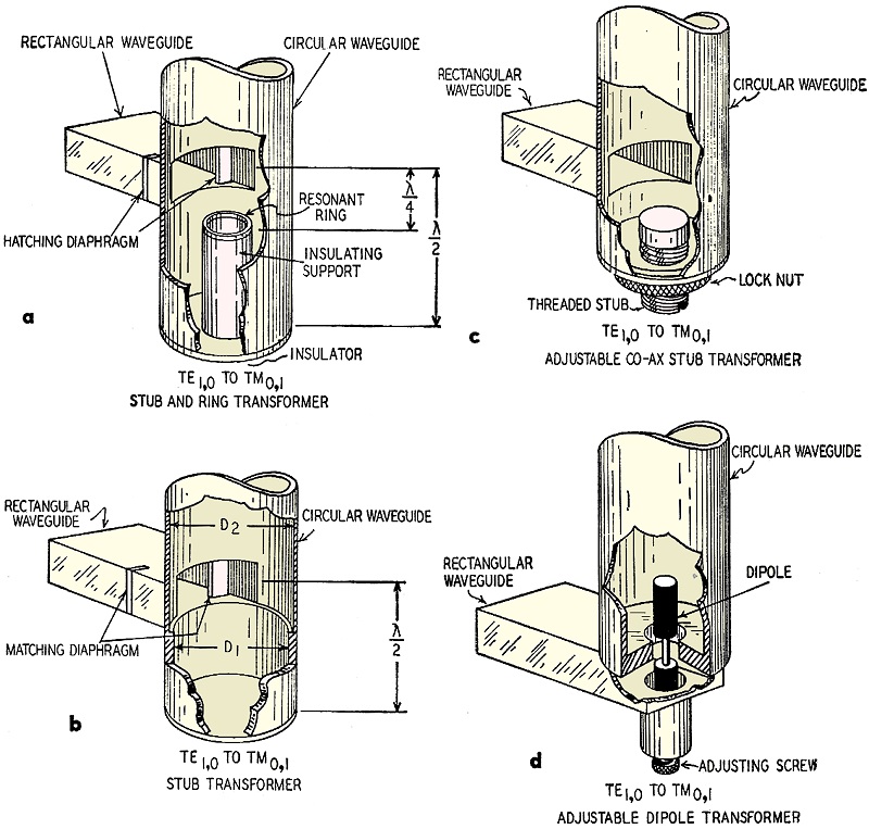
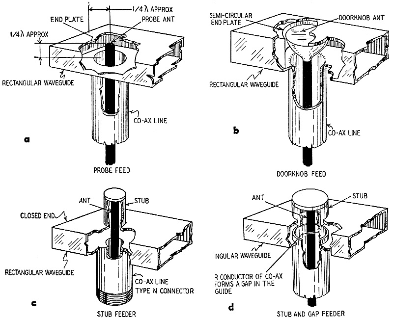
Fig. 3. - These are waveguide transformers used to match circular guides to rectangular ones. In changing from rectangular to circular guide a tapered section is generally used because a taper can include a gradual transformation of shape as well as size, as demonstrated in Fig. 1. A tapered section is used to transform from a rectangular guide of one size to one of another. The length of the taper determines the reflection introduced. In general the longer the taper the better, though short tapers can be used if the length is carefully chosen. Fig. 2 shows how standing-wave ratio decreases in an oscillating fashion as taper length is increased. It can be seen - as an example - that a ratio of taper length to wavelength of 0.98 is as good as one of 3.63, whereas a ratio of 1.2 introduces a standing-wave ratio of 1.09 compared to 1.03 for the long taper or the carefully chosen short one. A long taper is less frequency-sensitive than a short one and therefore is usually preferable. The second type of transformation is from the lowest mode of one size of guide to a higher mode in another, for example, from rectangular guide TE1,0 mode to round guide TE0,1. The main consideration here is that if a junction is formed between two kinds of waveguide, one of which will operate in more than one mode, then it must be considered that all the propagating modes will be set up at the junction. To correct this, it is desirable to construct the junction so that the desired mode is excited at a higher level than the unwanted ones. Further preference for the desired mode can then be introduced by the use of filters such as resonant rings, dipoles, etc., to limit activity of the undesired modes, and by the use of an inductive window near the junction to match the guide to the desired mode. Fig. 3 shows several examples of the above matching, using matching stubs, dipoles, and resonant rings to produce the desired results. At "a" are shown the stub and ring with the stub length equal to one-half wavelength and the position of the ring one-quarter wavelength for the TE1,1 mode. This results in suppressing the TE1,1 mode and supports the TE0,1 mode in the round guide. A matching diaphragm completes the transformer. At "b" the relation of diameter D1 and D2 with the stub and diaphragm suppresses the undesired, and supports the desired, mode. At "c" an adjustable stub is used while at "d" an adjustable dipole suppresses undesired modes. Wave Guide to Coax The third type of transformer is from waveguide to co-axial line or the reverse. Even though we have shown that the waveguide is preferable for frequencies above a certain point in the microwave region (see Part 1) there are occasions when it is necessary or desirable to feed a signal into or from co-axial line and connect this to a waveguide circuit. One case of this is in coupling magnetron tubes with co-axial feed to waveguide circuits. Fig. 4 shows several ways of transforming from waveguide to co-axial line. At a is shown a probe feed in which the center conductor of the co-axial line projects into the broad face of the rectangular waveguide approximately a quarter wavelength. The end plate of the waveguide being approximately a quarter wavelength from the probe, all power is radiated and adds in phase with that radiated directly down the guide. At "b" is a modification of the system at "a," but a "doorknob" is substituted for the probe for higher power. At "c" and "d" are two forms of stub coupling. A tuned probe projects through the waveguide into a stub that provides a large coupling loop linking all the flux between the co-axial center conductor and the waveguide end plate. The type shown at d provides an adjustment of the gap between the outer conductors to permit maximum coupling. Rotary Joints
Fig. 4 - Four waveguide-to-coaxial sections.
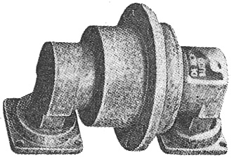
Commercial rotary unit for rectangular guide. Courtesy De Mornay Budd A specialized form of waveguide transformer is the rotary joint used to permit antennas to rotate through wide angles, yet prevent discontinuities that would rob power from the circuit. See the photograph on this page. The rotary joint provides a rotatable linkage that is symmetrical regardless of the angle of rotation and thus does not introduce strong reflections at one angular position and weak ones at another angle. To obtain this axial symmetry, the TM0,1 mode in circular guide is usually used since this is the lowest mode with the desired characteristic. In its most common form, rectangular waveguide fed at TE0,1mode is transformed in the rotary joint to TM0,1 in circular guide and thus connected to the antenna rotary elements. Another commonly used rotary joint utilizes a short section of co-axial line connecting two rectangular waveguides. The center conductor of this co-axial line projects into the guide of the rotary antenna at one end and into the waveguide from the transmitter at the other. Succeeding parts of this microwaves series will: continue the discussion of the waveguide apparatus; take up circuits and systems for transmitting and receiving using the apparatus we have discussed; review the types of antennas used for microwave frequencies; take up a study of microwave test equipment and methods of making measurements, and the problems of measuring power at these intriguing microwave frequencies. On p. 47 of last month's installment (numbered par. 6) we stated that "the wavelength in a waveguide ... is always greater than in air." This statement is correct, and the following explanation may clarify it: There are two velocities of energy propagation in a waveguide, namely, group velocity and phase velocity. Group velocity is less while phase velocity is greater than in free space. Group velocity refers to the propagation down a guide and must be less than in free space because the waves do not travel directly down the inside of the guide. They are reflected from one side of the guide to the other in zig-zag fashion. Thus the length of their path is the angular length instead of the axial length. As the operating frequency is increased above the waveguide cutoff frequency, group velocity approaches (but does not reach) the velocity in free space. Phase velocity is the product of frequency times wavelength. The wavelength in a waveguide is actually the distance between two planes of the same phase perpendicular to the direction of propagation. In a waveguide this is longer than in free space because of angular reflections. The apparent velocity is therefore greater for phase velocity than in free space.
Posted November 12, 2021 |
|