Microwaves Part VIII - Receiving and Transmitting Antennas
|
|
This is the eighth and final installment on a "Microwaves" series of articles in Radio-Electronics magazine by author C.W. Palmer. Each part is a stand-alone tutorial that does not rely on previous parts to be useful. Unlike most of the preceding articles that dealt in one way or another with waveguide, this final one concerns "receiving and transmitting antennas for microwave communication." It touches lightly on various types of antennas, field patterns, impedance matching, and applications. If you've been around for a while, you've likely seen it all before, but there are some nice photos of antennas designed and deployed by Bell Telephone Laboratories for their nationwide microwave telephone relay network. Bell Labs has done a lot of ground-breaking research in all aspects of communications technology - not just the phone on your desk (if you still have one, as I do). As a side note, you will probably notice that prior to the 1970s, it was common practice to not capitalize any letters in abbreviations other than the first if it was at the beginning of a sentence or title. Also, periods were inserted between the letters. To wit, here in this 1949 issue you will see "u.h.f.," "i.f.," and "d.b." rather than "UHF," "IF," and "dB," respectively. Microwave Series -- Part 1: How Radio Waves Can Be Transmitted Inside Pieces of Pipe (4/49), Part II: An Introduction to Standing Waves, Cavity Resonators, and Representative Examples of u.h.f. Plumbing (5/49), Part III: Tubes for the Microwave Frequencies, Giving Special Notice to the Lighthouse Triode, Velocity-Modulated Tubes, and the Magnetron (6/49), Part IV: How Waveguides Are Joined and Tuned for Lowest Possible Loss (8/49), Part V: Special Sections of Waveguide Are Employed as Transformers (9/49), Part VI: Some Equipment Used for Measuring Frequency, and Crystals for Receiver Frequency Conversion (10/49), Part VII: Action of Below-Cutoff Attenuators and of TR and Anti-TR Switches (11/49), Part VIII: Receiving and transmitting antennas for microwave communication. Part VIII - Receiving and Transmitting Antennas for Microwave Communication By C. W. Palmer
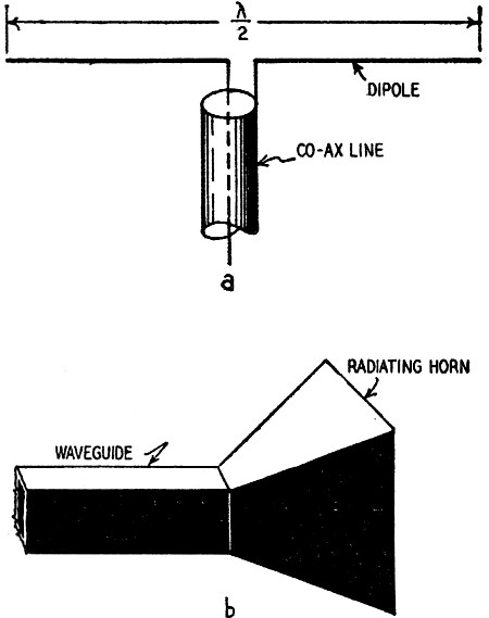
Fig. 1 - U.h.f. dipole and horn antennas.
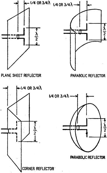
Fig. 2 - Reflectors concentrate the beam. Our study of microwave components cannot be called complete until the subject of antennas, both for transmitting and receiving, has been thoroughly explored. The usual considerations for antenna design at lower frequencies must be modified for microwaves. First, transmission distances are usually limited to the line-of-sight, which means about 20 to 50 miles, depending on the antenna height and the terrain over which the signals are to be sent. Second, microwave transmission usually is point-to-point rather than broadcast, so that it is desirable to use some form of beaming for the transmitting and receiving antennas. Third, the physical sizes of the antennas for microwaves lend themselves to efficient use of reflectors, directors, and multiple-unit radiators. And fourth, the extremely short lengths of microwaves permit the use of electronic lenses, which simulate in action the lenses used in optics to focus and concentrate light. Transmitting Antennas The simplest forms of microwave antennas are the dipole and expanded waveguide (horn) shown in Fig. 1. Both of these have a certain amount of directivity. The dipole has the usual bidirectional figure-eight pattern, while the horn has a unidirectional field-strength pattern. The dipole can be made unidirectional by placing a reflector behind it. A flat metal plate, a plate shaped into a parabola, a series of parallel rods about 0.1 to 0.25 wavelength apart, and other types of reflectors serve to focus the radiation from a dipole antenna into a beam that gives antenna power gain of several decibels. Fig. 2 shows a few of the reflector shapes commonly used. A group of stacked dipoles and a large reflecting sheet or series of deflecting rods provide still greater antenna gain than does the single dipole and reflector. These are stacked arrays. The increased efficiency of narrow-beam transmission permits the use of very low-power transmitters, because the power is concentrated rather than being spread over a large area. This is fortunate because it is difficult to generate high power in the microwave range. With the concentrated beam, the effective power sent out is very high compared to the actual transmitter output power, which in most cases is well under 100 watts. Using higher power is unnecessary because receiver gain - especially in the i.f. and a.f. sections - can be upped as needed, provided the signal at the receiving antenna exceeds the noise by a reasonable ratio. Atmospheric noise is a very minor problem at microwaves. Microwave Lenses While the reflector plates and rods described above follow to some extent the principles of optics in focusing a radio beam (somewhat as do the reflectors used in auto headlights and in searchlights), an even more striking similarity was recently demonstrated by the Bell Telephone Laboratories in disclosing their new microwave lens. Microwaves are focused in beams by being bent through sheets of insulating material and metal strips of the correct dimensions and shapes. Just as light waves can be bent in a glass lens to focus on a small spot, the microwaves are bent in this easily controlled focusing device, which produces efficiencies even higher than the reflectors and which is capable of handling a much greater bandwidth.
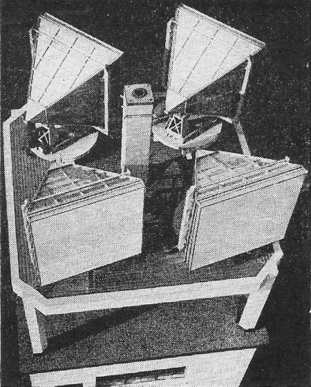
Fig. 3 - Four typical microwave lenses. Bell Laboratories photo
Fig. 4 - Cross section of magnetic lens.
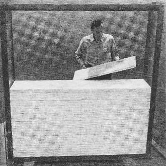
Fig. 5 - Putting together a metal lens. Bell Laboratories photo
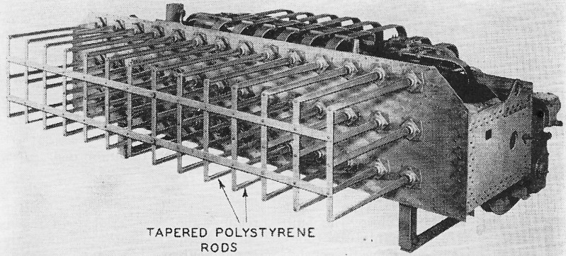
Fig. 6 - In this war-time end-fire array, the microwaves follow plastic rods. Bell Laboratories photo
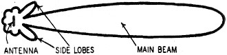
Fig. 7 - Ideal result is a narrow beam. This is not to be confused with the earlier Bell electromagnetic lens, pictures of which have been published in this magazine and in many Bell advertisements, especially around 1946. That lens worked on a waveguide principle and its frequency range was limited. The new lens might be called a true optical type, and the strips (or beads in some models) of metal in the lens look to the radio wave much the same as the molecules of glass in a standard optical lens look to the much shorter waves of light. Fig. 3 shows four of these lens antennas installed at a television relay station. At the base of the horn-shaped shield is the waveguide feed which supplies the r.f. power. The shield allows the waves to spread out over the entire surface of the lens which then focuses them into the narrow beam (vertically polarized) needed for the transmission path. As shown in Fig. 4, the lens consists of slabs or sheets of polystyrene foam (somewhat like sponge rubber in appearance). Thin strips of metal are inserted into slots cut into the foam in a predetermined pattern. The lengths and positions of the metal strips determine the sharpness and other characteristics of the beam. The construction of the lens is shown in Fig. 5. End-Fire Antennas Microwaves follow a plastic rod just as light waves follow a Lucite or fused-quartz rod. This phenomenon has been used to demonstrate the action of the waveguide many times, but has found little application in practical microwave work. However, one radar device developed during the war and used commercially for point-to-point microwave communication is the end-fire antenna, which makes use of this ability of plastic materials to guide waves. Fig. 6 shows a wartime version of the end-fire antenna. It contains three rows of polystyrene rods, 42 in all, each of which is fed by a waveguide from the transmitter. Such an antenna displays a remarkable ability to beam microwave signals and is easily controlled by correctly dimensioning the plastic rods. The number of rods, their length, and spacing depend on the width of the beam required and the power to be transmitted. These antennas have gains up to 17 db. Receiving Antennas The subject of receiving antennas can be covered very quickly: in most microwave installations the transmitter antenna is also the receiving antenna. Thus all the factors mentioned above except power-handling ability apply also to receiving. When separate receiving antennas are used, they usually take the form of a dipole backed up by some form of reflector. Where extremely sharp beaming is needed, the parabolic reflector or "dish" is generally employed while in the case of extremely wide-band work, such as television link receivers, the lens - used with either a waveguide or a dipole - is preferable. For the amateur radio experimenter, a dipole receiving antenna with either a flat or bent plate or rod reflector is probably the best. It is simple and fairly efficient. Antenna Matching For both receiving and transmitting it is necessary to match the impedance of a microwave antenna to the feed line for efficient operation. Let us consider a typical antenna consisting of a dipole mounted in a parabolic dish reflector. The position of the antenna in the dish is set for maximum gain and minimum side lobes. The side lobes are secondary responses which are always present in this type of antenna and, if large enough, will destroy its directional characteristics as well as reduce its efficiency. Fig. 7 shows a typical antenna field pattern for a highly directional beam with the main lobe and the side lobes marked. The antenna is matched to the feeder with impedance-matching transformers which were discussed earlier, in this series. For coaxial type feeds a quarter-wave transformer on the inner conductor is ordinarily used. Waveguides are matched by inserting a matching "window" at the proper place. A properly matched antenna feeder should have a standing-wave ratio of less than 1.2 after final adjustments. It is desirable to keep the r.f. feeder as short as possible to avoid losses. In many microwave installations, notably radar systems, the r.f. generator or transmitter is located very close to the antenna, with cables carrying d.c. power and modulation (voice, keying, or pulses) to the r.f. tubes. While this may seem troublesome to the amateur experimenter, the results pay many times over for the increased construction difficulties. Care taken in building the r.f generator will keep it small and light enough to mount right on the antenna mast or in a container at its base.
Posted September 25, 2020 |
|