Magnetometer at Work in Outer Space
|
|
Magnetometer at Work in Outer Space
Putting a magnetometer in a satellite, firing it into space, and getting data back is not a simple process, but electronics makes it work. By Dolan Mansir Varian Associates, Palo Alto, Calif. The complete Vanguard III satellite. It is now in orbit around the earth. Magnetometer is the name of an instrument for measuring magnetic forces or fields, especially weak fields such as the earth's. A simple magnetometer is a magnetic compass which measures direction. A slightly more complicated mechanism is a compass needle mounted on two jeweled bearings and carefully balanced for gravity effects. It can be used to measure the angle of the flux lines. Magnitude can be measured with a variety of instruments ranging in complexity from a bar magnet suspended on a quartz thread to the instrument described below. Intensity type magnetometers have been used for a number of years in geophysical exploration and submarine detection. In some geophysical applications the magnetometer is flown over a given area in a carefully plotted grid. Deviations from the ambient magnetic field for the area may indicate mineral deposits. Iron ore is most successfully located in this way. Of scientific interest is the fact that some magnetic materials imbedded in the earth are magnetized in a direction different from the direction of the earth's field in that area, indicating that some time in the earth's history the magnetic fields were somewhat different than they now are. The need to have a very accurate absolute measurement of the earth's magnetic field led to the development of the proton magnetometer, and advanced space technology spurred the development of magnetometers for space measurements.
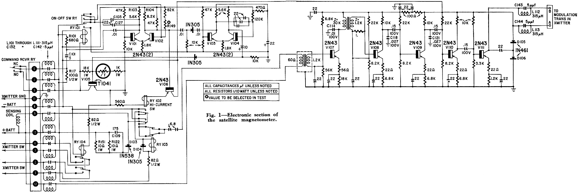
Fig. 1 - Electronic section of the satellite magnetometer.
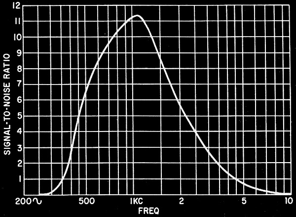
Fig. 2 - Typical response curve of the satellite's amplifier. Magnetometer in Space If you start a gyroscope spinning and then try to tip it over by giving it a push at the top or side, it won't fall over, but will start to wobble or precess. This simple principle can be used to explain the operation of the magnetometer now circling the earth in a Vanguard III satellite. The device, called a proton free-precession magnetometer, measures the earth's magnetic field above and in the highly ionized regions of the upper atmosphere. The measurements were telemetered on the US space frequency of 108 mc (the tracking transmitter on 108.03 me) to ground stations along the "picket fence" stretching from Blossom Point, Md., to the tip of Chile. The batteries on Vanguard III died Dec. 11, 1959. The Vanguard magnetometer was developed by Varian Associates, Palo Alto, Calif., for an NASA (National Aeronautics & Space Administration) group headed by Dr. James Heppner. Dr. Heppner was associated with the Vanguard program at the US Naval Research Laboratory until Oct. 1, 1958, when the project was transferred to the NASA. How a Magnetometer Works Protons are simply the nuclei of hydrogen atoms, and there are two reasons why they can be used to measure magnetic fields: Protons have magnetic moments, like very small bar magnets. They spin on an axis through their magnetic poles, or at least their behavior indicates they do. The magnetic moment and spin determine a property known as a gyromagnetic ratio. This merely means that the tiny bar magnets, spinning on their axes, will precess at a given frequency (like the gyroscope previously mentioned) if they are placed in a given magnetic field - if you follow the right sequence of steps to cause the precession to occur. The equation for the precession frequency, f, is: f (in kc) = H(in gauss)/0.234868 The constant 0.234868 is derived from the gyromagnetic ratio and f is an audio frequency relatively easy to telemeter. A nominal value of the earth's magnetic field is 0.5 gauss.
Fig. 3 - Magnetometer module used in the Vanguard III.
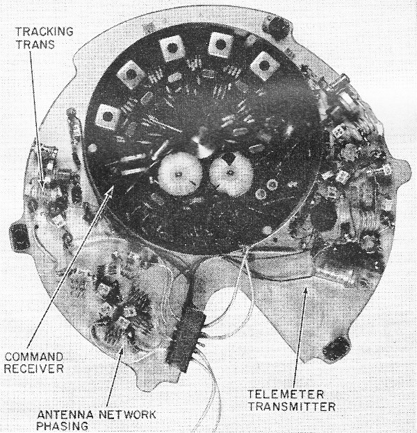
Fig. 4 - The command receiver, tracking transmitter and telemeter transmitter that went into the Vanguard III.
Fig. 5 - Major components in the Vanguard III satellite. Causing and Detecting Precession What does it take to cause a free precession and how do you detect it? If a bottle of water or other substance containing many hydrogen atoms is placed in a strong non-oscillating magnetic field, the nuclei of a majority of the atoms will align themselves with the applied magnetic field. Now, if the magnetic field is suddenly removed, the spinning atomic gyroscopes are given a "push" by the earth's magnetic field, and they start to precess in phase at a frequency given by the equation above. After about 3 seconds, the phase relationship is lost as the nuclei align with he earth's field and it is necessary to start over with the aligning process. If the aligning field is exactly in the same direction as the earth's field, the protons do not get a push and no precession occurs. For best signal amplitude, the aligning field should be at right angles to the earth's field. Alignment affects only the signal amplitude, not the signal frequency. In practice, the protons are actually placed in a bottle which is put in the center of a simple solenoid coil of wire. The coil does double duty - it furnishes the strong magnetic field to align (polarize) the protons, and the precessing magnetic moments of the protons induce the signal voltage in it. This is exactly analogous to an AC generator. In the satellite magnetometer, 7 amperes de is passed through the coil for 2.2 seconds. A relay then switches the current off and connects the coil to a high-gain band-pass amplifier which modulates the telemetry transmitter. The Vanguard satellite magnetometer has four essential parts: - A liquid abundant in hydrogen - A coil of wire - A switching circuit, called the programmer - A band-pass amplifier The liquid chosen for the satellite ride was normal hexane, commonly known as naphtha. It was picked chiefly because of its low freezing temperature. The coil was made of 600 turns of No. 15 HF (heavy Formvar) aluminum wire on a 1-inch diameter phenolic cylinder 4 inches long. The coil form serves as a bottle to contain the hexane, with phenolic end plates cemented to the ends of the coil with Armstrong A-2 adhesive. An O ring sealed brass screw plug in one end allows filling with hexane. This coil is exposed to the outside atmosphere, or the lack of it, when in flight. The entire outside of the coil is covered with an etched Faraday shield for RF shielding. Measurements on Command To conserve battery power, the magnetometer makes a measurement only on command from the ground. The programmer must respond to a momentary contact closure in a command receiver within the satellite, go through one polarize-measure cycle and turn off to await another command. When the command relay's contacts close, terminals 5 and 6 on the magnetometer are shorted (Fig. 1). RY101, the on-off switching relay is energized through R117. The contacts of RY101 do two things: they turn on the magnetometer circuits on command, and they keep C103 and C127 charged, via R103, while the magnetometer is off. When the command receiver relay drops out, after 0.1-second closure, RY101 is held energized by V105's collector current, and the magnetometer is held on. Immediately upon turn-on, the multi-vibrator (V101, V102) is triggered on because of the charge on C103 and C127. In a steady state, the multi-vibrator would be stable with V101 cut off and V102 operating near saturation. In the triggered state, V102 is cut off, resulting in a negative pulse of 2.2 seconds' duration at V102's collector. The negative pulse is directly coupled to V106's base, operating as an emitter follower with relay RY102's coil in the emitter circuit. RY102 is the high-current switching relay, so current is applied to the magnetometer coil and the protons are "polarized." The negative pulse at V102's collector is also differentiated and the trailing edge is used to trigger a second one-shot multivibrator (V103, V104), resulting in another negative pulse 2.2 seconds long. This pulse delays the turning off of the circuits while the precessing protons induce a signal into the magnetometer coil. This is the measuring time. The trailing edge of the second pulse (differentiated also) is coupled to V105's base, driving this transistor toward cutoff, and allowing RY101 to drop out and turn the magnetometer off. Relay RY103 is energized via RY102's contacts. RY103 disconnects the amplifier from the magnetometer coil during polarize time. Diode D104 slows RY103's contact reclosing time so the amplifier is reconnected to the coil only after transients caused by turning off the polarizing current have damped out. A circuit consisting of R151, R122, C109 and D103 is connected across the end to help damp out transients and limit the inductive current surge in the coil when RY102 opens. Another relay, RY104, is energized all the time the magnetometer is on. It turns on the telemetry transmitter. This saves battery power during orbit. If the command receiver should fail to open after a command, the magnetometer would stay turned on because RY101 is held energized. If this condition should last beyond the time when the magnetometer would normally turn off, the space experiment would be permanently finished, since the turn-off pulse would be ineffective, even if the command relay did eventually drop out. To safeguard the equipment, C101 is allowed to discharge through R101 to generate another trigger pulse to the first multivibrator, resulting in another polarize-measure cycle, when the command relay opens. Transmission of Data The amplifier boosts the signal level sufficiently to modulate the telemeter transmitter. The signal level induced in the magnetometer coil by the precessing magnetic moments of the hydrogen nuclei is in the order of 2 μV, so it is very important that the amplifier have a good noise figure. A combination of careful matching of the coil to the input base, choosing a low-noise transistor and operation of the first stage at high gain improves the amplifier's signal-to-noise ratio. The amplifier's frequency response is determined largely by coupling capacitors in the last three stages, and by bypass capacitors C114, C118 and C121. Unbypassed resistors in the emitter circuits help stabilize the amplifier gain for temperature changes. The amplifier output voltage is clipped by D105 and D106, to prevent overmodulation of the telemeter transmitter. The modulation transformer, V111's collector load, is located in the transmitter module. With a battery supply of 14.6 volts, the output voltage into a 600-ohm load will be 4.4 peak to peak. A typical amplifier response curve is shown in Fig. 2. The upper frequency limits are determined by the earth's magnetic field at Washington, D. C., and Cape Canaveral, Fla., where ground tests were made. The lowest precession frequency encountered in space by Vanguard III to date is 300 cycles, and the highest 1,600 cycles. Fig. 3 shows a completed magnetometer module. Terminals for external connections are in the rectangular area, and each terminal has a tuned trap (108 me) to keep RF out of the magnetometer circuits. The relay in the center of the circuit card is the high-current-carrying relay (RY102) and is placed in the center because it is the heaviest component. The printed-circuit board is perforated so the Eccofoam potting compound can cover both sides. Fig. 4 is a picture of a command receiver, tracking transmitter and telemeter transmitter. The transmitters were developed at Naval Research Laboratory for use with the Varian magnetometer. The command receiver, also developed at NRL, is used for a number of satellite experiments. Fig. 5 shows the major components in the satellite. The batteries fit in the bottom of the magnesium can in the lower hemisphere. The X-ray equipment sits on top of the battery pack. The potted magnetometer sits on top of the X-ray equipment with the transmitters and command receiver on top of the magnetometer. The satellite battery pack is made of Yardney Silvercels, partly because they are nonmagnetic. Battery capacities are designed so that batteries for all circuits should go dead about the same time. Probably the command receiver batteries will fail first. With a maximum of 50 commands per day, the magnetometer batteries were expected to last about 90 days (actual life was 84 days). The contributions of John Drake and Kelsey Robinson to the magnetometer development are gratefully acknowledged.
Posted March 20, 2023 |
|