Loudspeaker Crossover Design |
|
Loudspeaker Crossover Design
Greater realism through correct dual-speaker phasing - A direct approach to Loudspeaker Crossover Design By Norman H. Crowhurst Some points about the functioning of loudspeaker crossover networks should be clarified. Most classical treatments derive crossover networks from wave filter theory, which in turn is derived from the theory of artificial lines. The resulting designs may not satisfy all the requirements of a crossover network in the best possible way. The first and most obvious requirement of a crossover network is to deliver low-frequency energy to one speaker and high-frequency energy to another. This is usually taken care of reasonably well, using a roll-off slope to suit the designer's whim. A second factor (and one that often receives less attention) is the impedance presented to the amplifier by the combined network. Frequently this varies widely over the audio range and includes sizeable reactive components in the vicinity of the crossover frequency. To obtain best performance from the amplifier, a constant, resistive impedance should be presented to it as a load. The third requirement often receives even less attention. This is the realism of the acoustic output from the combination. While this is in some respects a matter of individual conditioning and preference, it depends fundamentally on certain electro-acoustic requirements. One of the most important, and frequently the one least considered, is the phasing, or apparent source of the sound output.
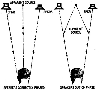
Fig. 1 - The apparent source of sound shifts when speakers are not in phase.
Fig. 2 - Examples of crossover networks for two-way loudspeaker systems.
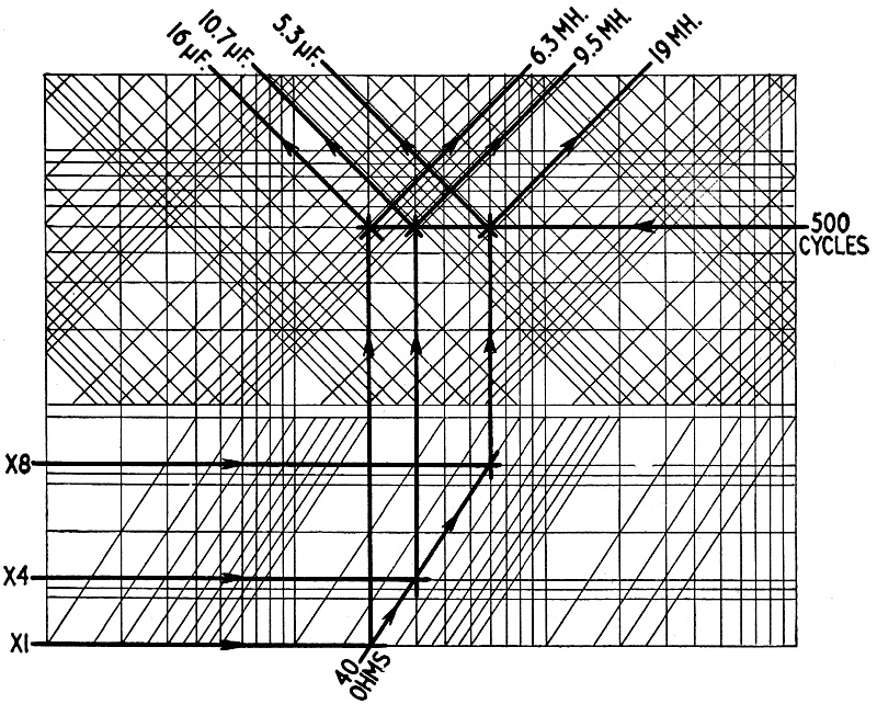
Chart for finding exact values of inductance and capacitance for any of the networks shown in Fig. 2. Use of the chart for a typical solution (Fig. 2-e) is illustrated in Fig. 3 on the opposite page.
Fig. 3 - How the chart on the opposite page [above] is used to find inductance and capacitance values for Fig. 2-e. Each speaker has a 40-ohm voice-coil impedance.
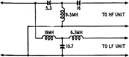
Fig. 4 - Crossover network component values for the circuit of Fig. 2-e derived by the method shown in Fig. 3. Tests have shown that phase distortion with single speakers is not normally detectable, but when two sources are employed, the phase relations between them influence the character of the radiated sound field. The frequency response as registered by a good pressure microphone may be flat, but what about the wave-shapes? The pressure microphone does not answer that, but a pair of human ears can detect such phase peculiarities, and failure to consider this factor has made many dual-unit combinations sound noticeably unreal, even though their frequency response may look perfect, and there may be no measurable distortion. Source of the Sound The reader may have checked two speakers for phasing by listening to them while connections to one of them are reversed. Standing some distance in front of them, on the center line (as in Fig. 1), when they are correctly phased the sound seems to come from a point midway between the two units; but when incorrectly phased, two effects can be noticed: There is a deficiency of low frequencies (due to cancellation effects) and the source of sound at higher frequencies no longer seems to be associated with the units actually radiating it. This is because the air-particle movement caused by the radiated sound is no longer back and forth along a line from the common source, but approximately at right angles to it. The sound field around the listener's head is perpendicular to what it should be, causing, through our binaural perception, the confused impression which may be called "dissociation effect." A similar dissociation effect will occur with dual units driven by a crossover system, at any frequency where the two speakers are out of phase. It is best to keep the two units close together. Some favor putting the smaller unit on the axis of the larger one and immediately in front of it. But, however the units are arranged, the dissociation effect can become noticeable if there is an out-of-phase condition at some frequency near the crossover point. The relative phase at crossover can be adjusted by positioning the diaphragms on their common axis so the wave from the low-frequency unit emerges in phase with that from the high-frequency one. When the units are mounted side by side on the same baffle, the sound should emerge in phase at the baffle surface. Constant-Resistance Networks But how does the crossover network affect the relative phase at frequencies near crossover? This question often seems to be overlooked, and neglecting it can cause the trouble just described. Some networks, of the kind employing two or more reactances for each unit, have values adjusted to give an accentuated frequency rolloff. For example, the networks shown at Fig. 2, c and d, using values given by the chart in this article, are of the constant-resistance type, giving a rolloff of 12 db per octave; the phase difference between the outputs is always 180 degrees; but using values designed for a sharper rolloff, the phase difference is not the same. At frequencies near crossover, phase difference changes rapidly. Some out-of-phase effect in the vicinity of the crossover frequency is unavoidable unless a constant-resistance type network is used. It is fortunate that this type takes care of both the second and third requirements mentioned above. The chart may be used to design any of the six types of crossover network illustrated in Fig. 2. Those at a and b give a rolloff of 6 db per octave and a constant phase difference of 90 degrees. For best results the positions of the two diaphragms should be adjusted so the difference in their distances from the face of the baffle is about one-quarter wavelength at the crossover frequency. The phase difference will not be serious within the range where appreciable energy is coming from both units. The networks at c and d give a rolloff of 12 db per octave, and a constant phase difference of 180 degrees, which means that reversing connections to one unit will bring the phase right. The units should be mounted so their diaphragms are in the same plane. For cases where the frequency response of the units used requires a roll-off steeper than 12 db per octave, the networks shown at e or f are recommended. These give a rolloff of 18 db per octave, and a constant phase difference of 270 degrees. This means that mounting the diaphragms a quarter-wavelength apart at the crossover frequency will give in-phase outputs by appropriate connection. All these networks are designed to present a constant, resistive impedance to the amplifier over the entire frequency range. The Impedance Varies One more point is often overlooked: The networks are designed on the theory that they are feeding resistance loads of the same value as the nominal voice-coil impedance. The voice-coil impedance is not pure resistance, so the performance of the networks is altered. The most serious effect is usually due to the inductance of the low-frequency unit voice coil. By using networks a, d, or e, each of which feeds the low-frequency unit through a series inductance, this effect can be overcome by subtracting the voice-coil inductance value from the network inductance value derived from the chart. Even if the available data is insufficient to allow this, these networks will minimize the effect, because the inductance of the voice coil will add very little to the effective inductance of the network. In the other networks the shunt capacitor combined with the voice coil inductance will cause a greater variation in input impedance. Each diagram in Fig. 2 has the inductors and capacitors marked with symbols. These identify the reference line (in the bottom part of the design chart) to be used for finding each component's value. Fig. 3 illustrates the use of the chart to find values for a network of the type of Fig. 2-e, and Fig. 4 shows the actual circuit calculated in this way for a crossover frequency of 500 cycles, at 40 ohms impedance. The input impedance is the same as each speaker voice-coil impedance. Some prefer to design the crossover network for 500-ohms impedance and use matching transformers at the outputs to feed the individual voice coils. This method has two advantages: The two units need not have the same voice-coil impedance; and smaller capacitors can be used. The range of impedances covered by the chart extends up to 500 ohms to include such designs. One modern trend has been to use separate amplifier channels for each unit. In this case the chart can be used for designing an inter stage filter to separate the channels, by making the following adjustments: multiply all impedance values by 1,000 (this means the impedance used to terminate each output as a grid shunt); change inductance values to henries instead of millihenries; divide capacitor values by 1,000. Suitable networks for this application are a, c or e, since these allow the input to each amplifier circuit to be grounded on one side. The characteristics of the final out-put from any type of network and combination of speakers can only be predicted accurately if the source (amplifier) impedance is known. This can be measured with simple equipment by the methods described in the article "Audio Impedance Measurements," by James A. Mitchell, in the April, 1952, issue of Radio-Electronics. The amplifier impedance should be as low as possible, and practically constant over the entire frequency range to be reproduced. With present-day components, this can be achieved only by using multiple low-impedance output triodes, or by carefully-designed inverse feedback circuits. The series of articles "Audio Feedback Design," by George Fletcher Cooper (Radio-Electronics, October, 1950 - November, 1951), covers many applications of feedback to amplifier circuits.
Posted April 11, 2022 |
|