Inertial Guidance Directs Planes and Missiles |
|
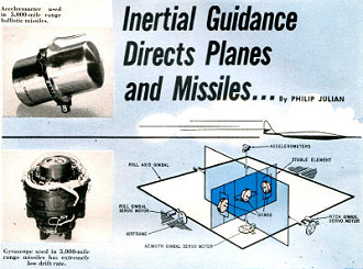
Inertial Guidance Directs Planes and Missiles Fig. 2 - The stable platform consists of two or three gyroscopes, plus two or three accelerometers mounted in a gimbal arrangement which allows gyros to keep the accelerometers fixed in space, no matter how the vehicle moves. (Courtesy of Aviation Week) (top) Accelerometer used in 5,000·mile range ballistic missiles.
By Philip Julian Electronic computers, gyroscopes and accelerometers, when properly combined, form a sensitive guidance system that leads a guided vehicle to any spot on earth. A new technique called "inertial guidance" enables man to match the ability of birds to navigate unerringly over distances of thousands of miles without using radio or radar. Furthermore, the inertial-guidance system can operate in weather so bad that the birds are grounded. Inertial guidance will direct our new intercontinental ballistic missiles (ICBM's) to targets 5,000 miles away and will also direct our newest bombers, the supersonic B-58 and hypersonic B-70, to their targets. It recently was used to guide the submarine Nautilus on its polar mission. An inertial-guidance system is completely self-contained in the missile or airplane. It does not require ground-based radio or radar stations for assistance, nor does it radiate any electromagnetic energy itself. Inertial systems do, however, make extensive use of electronics. There are a variety of possible inertial system configurations, depending upon the intended mission. However, all operate on the same basic principle - measuring accelerations of the missile or airplane throughout the guided portion of its flight. From these measured accelerations an airborne computer system can calculate how far the vehicle has traveled and in what direction. The only data the inertial system computer needs is the position of the target relative to the takeoff point. The computer then continuously calculates the vehicle's position, compares it with the desired course-to-target, and generates signals which automatically steer the vehicle onto the correct course .
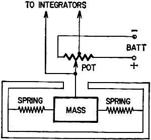
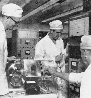
Fig. 1 - Cutaway view of a simple accelerometer. Any acceleration of the vehicle in which the device is mounted causes the mass to be displaced from the center, producing a signal which is proportional to the acceleration. Because inertial systems are completely self-contained, do not themselves radiate any electromagnetic energy and do not need ground-based radio-radar stations, they offer several important military advantages: Jam-proofness: There is no known way to jam or confuse an inertial system. By contrast, guidance systems which use radio or radar can be jammed or disrupted by enemy electronic countermeasures equipment. Security: Unlike radio-radar guidance whose electromagnetic radiation tips off enemy that the vehicle is coming, making it possible to launch intercepting aircraft or missiles, inertial guidance gives no advance warning to the enemy. Mobility: Since inertially guided missiles require no large ground-based guidance system installations, they can be launched from hidden sites or quickly moved to other locations. Certain limitations or disadvantages are, however, inherent in inertial systems. For example, an inertial system is extremely costly because of the extreme precision required to fabricate its components. Also, errors build up with time, so accuracy is reduced on long missions. However, there are ingenious ways for getting around this problem. How does it work? To understand how an inertial system operates, we must first examine the basic fundamentals. These are quite simple. If you were told that an automobile had started from rest and was accelerating uniformly at the rate of 10 feet per second every second, you could calculate its distance at any given instant. The formula is: Distance = 1/2 at2, where a is acceleration and t is time. For example, after 1 second the car will have covered a total distance of 5 feet (1/2 x 10 x 1). At end of 2 seconds the auto will have moved a total of 20 feet, and after 3 seconds a total of 45 feet. If the car were equipped with a device which could measure and indicate the acceleration, and if we had a stop watch, scratch pad and pencil, we could always calculate how far we had traveled. Naturally, in a car equipped with an odometer-speedometer, there is no point in going to such trouble to determine how far we have traveled. But in an airplane or missile there is no such easy way of measuring distance covered and hence we turn to inertial guidance. An inertial system continuously runs through the mathematical calculation of the D = 1/2 at2 equation. Measuring acceleration To perform this computation, the inertial system must continuously measure vehicle acceleration relative to the earth. To do this, the system employs devices known as "accelerometers." One of them is installed in the aircraft or missile to measure accelerations along its fore-aft axis. Another is installed so as to measure accelerations at right angles to the fore-aft axis - corresponding to a line drawn through the vehicle's wings (or where its wings would be if it had them). In certain applications, primarily ballistic missiles, a third accelerometer is installed to sense accelerations at right angles to the other two, essentially up-down accelerations relative to the earth. In principle, these accelerometers are very simple devices, but in practice they become very complex to achieve the extremely high sensitivity and accuracy required. The simplest type of accelerometer consists of a weight (mass) which is suspended in an enclosure by two springs (see Fig. 1). When the accelerometer is at rest (zero acceleration), the mass is centered relative to its enclosure by the supporting springs. If the enclosure is suddenly moved along its sensitive axis (line running through springs and weight), the weight will try to "sit tight," until it is forced to come along with the enclosure by the forces exerted by the springs. This follows Newton's laws of motion which say that a body at rest tends to remain at rest unless acted upon by outside forces. The amount that the weight is displaced from its center (zero-acceleration) position inside its enclosure is in direct proportion to the magnitude of the acceleration applied to the enclosure. If a small electrical pickoff (potentiometer, synchro, etc.) is added to measure displacement of the weight from its center position, the signal generated by the pickoff will be proportional to acceleration, and the complete device will function as an accelerometer. Because the accuracy of the inertial guidance system can be no better than the accuracy of its accelerometers, more elaborate and more complex accelerometers than the one described must be used. The problem is made more difficult because of the wide range of accelerations the device must measure - from perhaps 100 G (100 times the acceleration of gravity) to a few thousandths or millionths of a G. Some inertial systems employ what are called "integrating accelerometers," which sense acceleration and simultaneously perform the operation of "integration" so that their output signal is directly proportional to the vehicle's velocity or distance traveled. The integrating accelerometer is more complex than the elementary accelerometer, but simplifies the calculations which must be performed by the system's computer. In one respect, Nature appears to have conspired to make inertial guidance systems impractical. This problem arises because the accelerometer which reacts to the vehicle accelerations it seeks to measure also responds to the force of gravity which it should ignore. Thus an accelerometer intended to measure horizontal accelerations along the fore-aft axis of an airplane or missile would correctly sense no acceleration when the vehicle is at rest, so long as the accelerometer is truly horizontal. But if the vehicle and accelerometer were slightly off level, the accelerometer weight would be deflected from center by gravity, and the inertial guidance system would "think" the vehicle had taken off when in fact it was still at rest. If this were the extent of the problem, it could be easily solved by leveling up the accelerometers before turning on the inertial system prior to takeoff. But even if this were done, the missile or airplane obviously is not going to maintain a perfectly level attitude once it has been launched. The basic problem, then, is how to keep the accelerometers in position throughout the mission to prevent them from sensing gravity and confusing it with acceleration due to actual vehicle motion. For a solution, inertial system designer - turn to the gyroscope, a device that tries to hold its angular position always fixed in space. The simple spinning top, or the toy gyro which children find so amusing, demonstrates this principle. The stable platform A basic gyro consists of a small flywheel spun at extremely high speeds, usually by an electric motor. The shaft about which the flywheel rotates is called the "spin axis," and it is this which the gyro seeks to hold fixed in space. Inertial guidance gyros, accelerometers and other critical components are assembled, inspected and tested in air-conditioned dust-free rooms to prevent contamination and resultant inaccuracies. If the gyro's spin axis is supported in a suitable frame, called a "gimbal," and this frame is in turn supported inside a larger gimbal, so that the outer frame can be rotated freely about the inner spin-axis gimbal, we have a simple gyro. In practice, many gyros have still a third gimbal which supports the other two. When the gyro's flywheel has been brought up to speed, the outer gimbal (s) can be rotated or moved to any position without disturbing the position of the spin axis - just as if it were locked onto a distant star. If such a gyro is installed in an airplane or missile, with its supporting gimbal (s) attached to the vehicle's structure, the gyro will try to keep its spin axis fixed in space regardless of changes in vehicle attitude during the flight. If the spin axis is aligned with the true vertical before takeoff, the gyro will seek to hold this same position throughout the mission. And if the accelerometers are, in effect, mounted on the gyro spin axis (at right angles to it), they will remain horizontal throughout the flight and cannot sense the unwanted gravity acceleration. If another gyro is installed so that its spin axis is horizontal, instead of vertical, and aligned with true north, this gyro will try to keep itself aligned with north during the flight. This provides a heading reference by which the inertial system can resolve vehicle movement into distance traveled in north-south and east-west directions. Inertial systems usually employ two or three gyros, depending upon the type of gyro used. There are certain advantages and disadvantages to each type of configuration. The combination of gyros, accelerometers, their supporting gimbals and related mechanisms is called a "gyro-stabilized platform," or sometimes "stabilized platform," for short (see Fig. 2). Gyro drift If gyros kept their spin axes fixed in space indefinitely, the problem of designing an inertial system would be easy, but once again Nature conspires to make the problem difficult. In practice, a shift in the position of the spinning gyro flywheel on its shaft of a few millionths of an inch can make the gyro wander ("drift") from its original position. A speck of dirt or a metal chip too small to be seen by the human eye, except through a microscope, in one of the gyro gimbal bearings can also introduce serious errors in gyro performance. Any such drift in the position of the gyro spin axis tilts the accelerometers off horizontal, causing them to sense gravity acceleration, or shifts the heading reference, making the system think the vehicle is moving in a different direction than it actually is. At the end of World War II, the gyros used in aircraft flight instruments (to indicate airplane attitude and heading) had drift rates of about 15° per hour. If inertial systems used such gyros, guidance accuracy would be completely unacceptable. Today, industry builds gyros which have drift rates of only .01° per hour. Such a gyro has less drift after 2 months of operation than the post-war flight gyros experienced in a single hour. Gyros with still lower drift rates are under development. To build such extremely accurate gyros, manufacturers must assemble them in ultra-clean air-conditioned rooms where the air is continuously filtered to keep out microscopic-size particles of dust. Employees must wear lint-free nylon hats and coveralls, and coats and tools are cleaned at least once a day. No one can enter without passing through airlocks equipped with high-power blowers which dust him off thoroughly. Individual parts that go into the gyro are inspected under microscopes for possible burrs which might work loose and find their way into bearings. Deburring is done under a microscope, using precision dental tools. The thinking heart The heart of any inertial system is the computer which integrates acceleration signals to determine distance traveled, resolves this into distance covered in north-south and east-west directions, then compares this with the path the vehicle must fly to hit its target, and finally it calculates what signals must be sent to vehicle's controls to maneuver it onto the desired course. These computations must be performed from takeoff throughout the guided portion of the mission. For a ballistic missile, where guidance lasts only several minutes (from there on the missile behaves like an unguided projectile), the computer must work at lightning speed and with extreme accuracy. Unless errors in missile path are quickly corrected, the missile may go out of control or miss the intended target by a wide margin. Most of the new inertial systems under development use tiny digital computers. These are first cousins to the familiar giant computing brains, but have been so miniaturized that they occupy no more than a couple of cubic feet in volume. Some of the newer airborne digital computers for inertial system use occupy less than 1 cubic foot. To reduce computer size, designers have gone to all-transistor models. One such computer, being developed for intercontinental ballistic missiles, uses approximately 1,200 transistors and 10,000 diodes. Choice of targets is made by plugging appropriate subassemblies into the computer. Schuler-tuned systems Although industry's designers have made remarkable progress in the past 10 years in improving the performance of gyros and accelerometers, an extremely stiff price must be paid in terms of manufacturing and inspection cost to hold down errors in inertial systems intended for use on long missions. For example, an inertial navigation-bombing system for use in a 1,000-mph bomber, like the B-58, must maintain good accuracy for 5 hours to reach a target 5,000 miles away. This is more than 60 times the period that an inertial system must provide guidance for an ICBM. This means that gyro drift errors accumulate for 60 times as long and hence can be something like 60 times greater. Fortunately, Nature lends a helping hand here in the form of a principle first suggested in 1923 by Dr. Maxmillian Schuler, a German professor of applied mechanics. Applying this principle of the "84-minute pendulum," to provide what often is called a "Schuler-tuned" inertial system, greatly reduces error buildup on long missions by effectively washing out gyro drift and some, but not all, of the accumulated errors approximately every 84 minutes. Hybrid systems Even with Schuler tuning, it is not easy to get the high-precision accuracies required for long military missions. Another approach which eases the accuracies required of gyros and accelerometers is to combine the inertial system with some other navigation technique to form a hybrid system. One such hybrid system uses a small airborne Doppler radar which measures the vehicle's ground speed accurately. The Doppler radar is used to correct for errors in acceleration measurement while the vehicle is over friendly territory where its electromagnetic radiation does not give it away. Once the vehicle approaches enemy territory, Doppler radar can be turned off and the system operated as a pure inertial system. Another possible hybrid system configuration combines inertial and celestial navigation techniques. Electro-optical devices are available which automatically track a star, determining its azimuth (direction) and elevation position. Two such devices, together with a vertical reference such as a stabilized platform provides, furnish enough information for a computer to calculate the vehicle's position. Such periodic star fixes can be used to correct any accumulation of errors in the inertial system when suitable stars are available for sighting. When clouds prevent obtaining a star sight, the system reverts to its pure inertial mode of operation. Size, weight and cost of an inertial guidance system depend upon its intended use, including such factors as mission duration and required accuracy. Although exact figures are not available because of military security considerations, an inertial guidance system for ballistic missiles is believed to weigh between 400 and 500 pounds, including the computer. A single system probably costs in the neighborhood of $250,000. With developments now under way, weight of such an inertial system ought to come down to perhaps 200 pounds and its price down to perhaps $150,000. For short-range uses, such as in helicopters for navigation where mission times are measured in minutes and extreme accuracy is not required, it is possible to build an inertial guidance system today which weighs less than 100 pounds. Despite its weight and price, which are high compared to other navigation guidance techniques, the many attractive military advantages of inertial guidance suggest it will find increasing use in new military missiles and aircraft.
Posted December 14, 2021 |
|


