Indoor Television Antennas |
|
See another point of view entitled "Indoor and Built-In Antennas - Their Strong and Weak Points," by Ira Kamen, in the November 1949 issue of Radio-Electronics. Indoor Television Antennas Outside antennas are not always necessary for acceptable television reception. By Edward M. Noll and Mathew Mandl Occupants of apartments where roof antennas are prohibited must use either an indoor or a window antenna to receive television programs. These antennas are satisfactory in areas where the signal strength is high, and with proper choice of type, dimensions, and positioning, can be made to work fairly well on weaker signals also. Occasionally they perform passably even in fringe areas, especially if the location is high or the receiver is located on an upper floor. Despite the type used, indoor or window antennas will not perform miracles, and at best they rarely come up to a well planned and erected outdoor antenna.
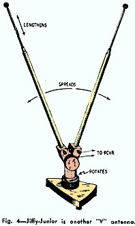
The window antenna is preferable to the indoor type because it can be made more elaborate. Because it is usually placed in a less confined area, it can deliver a stronger signal to the receiver. An indoor antenna must be placed where the troublesome multiple reflections within a building do not cancel, but reinforce to give the best signal. There is also appreciable absorption and shunting of signal by the building structure before it reaches the indoor antenna. Similar troubles, of course, often plague the window antenna - particularly if it must be mounted on the side of the building away from the transmitter. This condition is aggravated if an intervening structure blocks the signal path. The window antenna is often subject to reflections when it is placed among structures as high as or higher than it is. Distant reflections put ghosts on the screen, while the multiple close reflections to which window and indoor antennas are especially liable disturb the resolution and sensitivity of the antenna. A window antenna on the proper side of the building and with a clear path toward the TV stations will give excellent performance. Existence of the several variables mentioned above means that an experimental approach must be used. Location and orientation of the antenna is certainly every bit as important as the actual choice of antenna type. Selection and Installation To obtain full benefit from the weak available signal, the importance of proper antenna dimensions and impedance matching cannot be over-emphasized. An adjustable type should be chosen which can be tuned to the various TV channels to be received. The weaker signals can then be "tuned in" exactly - which means a substantial increase in picture quality. The antenna transmission line should be ideally matched and of proper over-all length to deliver the signal to the receiver at maximum strength. In the weaker signal areas, a booster improves performance of a window or indoor antenna, particularly if the signal-to-noise ratio and sensitivity of the booster are high. Orientation and positioning of the antenna are very important for best results. There are definite space patterns for the various stations in any locality. Position the antenna at various trial points while checking the signal strength by watching picture reception. The many reflections inside and near walls indicate that space loops are closer together and less intense than those encountered outdoors. Because of these multiple indoor reflections, correct orientation of an indoor antenna is not always truly broadside to the direction of the station. Experimental tests must be made before the best placement is found. Thus, the most can be secured from an antenna which has adjustable dimensions, can be moved about readily and mounted at unusual angles, and can be flexed into various positions after mounting. Trial and error alone can determine the best place within a room and the most satisfactory antenna-arm positioning. Home-Made Indoor Antennas The television technician can use his ingenuity in constructing effective indoor antennas for customers who can- not use outdoor installations. Twin-lead, 300-ohm line lends itself well to indoor antenna construction because it can be concealed easily. It can be mounted on the molding or around the window frame, or even placed under the carpet because it lies flat. It can be cut to proper length (depending on the channel frequencies allocated to the area) and connected as a folded dipole. Harmonic relations usually make good reception possible on the higher channels even though the antenna is cut for a low channel. Channel 10, for instance, is the third harmonic frequency of channel 3 and can be received well with an antenna cut for that channel. When making a folded dipole from a 300-ohm, twin-lead transmission line, consider the velocity constant of the insulating material. Short each quarter-wave side of the folded dipole (Fig. 1), at a point obtained by multiplying the quarter-wave physical dimension of the antenna by the velocity constant of the dielectric material. Shorting at this point, although it does not change the over-all length of the folded dipole produces additional signal strength because of the effect of the velocity constant on the circulating current in the antenna. For example, a folded dipole on channel 10 would have an over-all length of approximately 29 inches, this representing a half wavelength. Each side therefore, would be 14½ inches. The short is placed at a point obtained by multiplying the velocity constant by 14½ inches. If the velocity constant is 82%, a short would be inserted on each side about 11.9 inches from the center of the antenna. Circular or rectangular antennas for indoor mounting can also be made with No. 14 to 18 wire. Such an antenna can be concealed behind a picture, or the wire can be run around an entire window frame. Again, tests should be made before installing such an antenna permanently, because orientation may be incorrect. Airplanes and Ignition Fig. 2 shows the relative patterns of a single dipole and a stacked dipole. This is an end view with the observer's eye level with the antenna. The pattern is the same for both the dipole and folded dipole. Note that single antennas have pickup characteristics in the horizontal (the desired) direction and vertical (undesired) direction. The vertical pickup properties make this type of antenna sensitive to ignition noise from below and airplane interference from above. Ignition noise results in streaks across the picture, and airplanes cause rapid fading of the picture in and out. The stacked array is much better, because of its elongated horizontal pattern and low sensitivity to pickup. Indoor or window antennas, however, do not lend themselves to stacking because of limited available space. If interference is severe, a loop antenna is recommended, for it is the only antenna which the authors have found to have the elongated horizontal pattern of a stacked array. This circular loop must be exactly a wavelength in circumference, must be absolutely vertical, fed at exact bottom, and critically orientated. The gain is high and the performance unusual. (See "Antennas for Television, Part VI," Radio-Electronics, June, 1949, for further details and channel dimensions.) This type can be made from No. 14 wire and easily concealed behind drapes or furniture. Commercial Indoor Antennas One of the most common indoor antennas is the simple dipole made of telescoping rods. This antenna can be adjusted to proper length and mounted on a stand. The antenna rods can also be swung to various angles for best reception. Typical examples are those manufactured by JFD Co. and Ward, shown in Figs. 3 -a and 3 -b. Another ex- ample of this type is the Jiffy -Junior put out by Delson (Fig. 4). It has a stand with rubber suction cups on the bottom to hold the base firmly to any surface. Occasionally this antenna can be used at the window simply by pressing it against the pane. Tricraft Products manufactures two special antenna types, (Figs. 5 -a and 5 -b), one of which is flat and mounts under the carpet or behind drapes. The second indoor type is tunable with a selector switch which is set on the desired channel. This antenna is one fifth the length of an ordinary channel-2 dipole, yet it is tunable to the low- and high-frequency television bands. Another unusual antenna (Fig. 6) manufactured by Radio Craftsmen consists of a folded dipole which opens up much like a metal -tape rule. The various channel numbers are recorded on the metal tape so the antenna can be opened up into a folded dipole of the proper length for the channel to be received. The arms are fully retractable, just like a metal tape measure, which in a way it is. Jerrold Corporation manufactures a combination indoor antenna and booster. The antenna is a telescoping dipole which mounts directly on the back of the booster amplifier, and is an integral part of the whole unit. This is perhaps an ideal arrangement in the weaker-signal areas when an indoor antenna must be used. The RCA tube department recently announced a new type of indoor antenna employing end-loading disks which reduce over-all length and still permit reception of low-band stations. Large spheres or flat disks at the end of an antenna increase the effective area at the end and thus increase the capacitive component of the antenna (referred to as "end effect "). Then, the inductive component, represented by the total length of the antenna, can be correspondingly smaller to resonate at a given frequency. This type of antenna functions well on the high-frequency channels because its physical length corresponds to a half-wavelength on these channel frequencies. A Built-In Antenna Philco has just announced that their latest receivers include built-in antennas, and it is likely that other manufacturers will have followed their example before this is printed. The foregoing commercial indoor types are the result of much research and clever design by manufacturers, and often produce excellent results. But it should be emphasized again that, if the location is in a fringe area and near ground level, not much can be done to secure a completely satisfactory picture. For really long-range reception, of course, the indoor type of antenna is out of the question. A roof antenna is preferable; if it cannot be used, the window type is the one that must be installed. Commercial Window Antennas Many standard dipoles and folded dipoles commercially available for roof mounting have special mounting brackets which adapt them to window mounting also. There are a few special window-type antennas such as the Jiffy-Tennas manufactured by the Delson Manufacturing Co. (shown in Fig. 7) which can be mounted to the window frame by a screw expansion system which holds it firmly. One type consists of a folded dipole director or reflector combination with sliding rods and trombones to permit adjusting the length for optimum reception of a specific channel. The antenna can be readily moved and oriented for proper positioning. The small element can also be used as an independent high-band dipole and the folded element as an independent low-band folded dipole. The smaller dipole is individually adjustable as to positioning and can be set separately from the folded dipole for ideal reception of a high- frequency station. This is necessary in many locations. A second type of window antenna consists of a high- and low-band dipole, also independently adjustable as to length and orientation. In this form the high-band dipole is stacked above the low-band dipole. While there is less opportunity to position a window than a roof or indoor antenna, it can be tried on each side, below, and sometimes above, each of the available windows. Many private home housing projects prohibit outdoor antennas. In such instances indoor antennas should be placed in the attic -if there is one - rather than in the room where the receiver is located. Height is always a dominant factor in increasing signal strength, and versatile antenna types can be mounted in the attic at the apex or some other convenient point underneath the roof. The antenna should, of course, be checked in various positions and adjusted for correct length and orientation to obtain the best possible performance. Summary All indoor and window types suffer by comparison with the high outdoor types, and installation precautions must encompass all possible means to secure the most from these devices. However, when an indoor or window antenna takes full advantage of installation, impedance match, orientation, and the other factors detailed in this article, it sometimes performs as well or better than an outdoor antenna poorly installed in terms of orientation, impedance match to receiver and position.
Posted November 24, 2021 |
|

 If he finds it necessary to install an indoor or window antenna due to housing
restrictions, the television technician and dealer has the additional responsibility
of making sure the customer gets a receiver with superior sensitivity. There are
wide differences in the comparative sensitivities of commercial television sets.
If an indoor antenna is used, best performance is obtained when receiver sensitivity
is high and signal -to -noise ratio of the r.f. tuner above average.
If he finds it necessary to install an indoor or window antenna due to housing
restrictions, the television technician and dealer has the additional responsibility
of making sure the customer gets a receiver with superior sensitivity. There are
wide differences in the comparative sensitivities of commercial television sets.
If an indoor antenna is used, best performance is obtained when receiver sensitivity
is high and signal -to -noise ratio of the r.f. tuner above average.