Hall Effect in Solid State
|
|
At this point in time, it's hard to imagine an article "introducing" the Hall effect to electronics enthusiasts, but that's the opening statement in this 1968 Radio-Electronics magazine piece. Although Mr. Edward Hall first discovered the eponymous phenomenon in the late nineteenth century, his work was with metals, which exhibit a rather small reaction to the application of a magnetic field on a conductor with current flow. The emphasis in this article is on semiconductor-based Hall effect sensors which produce a much larger change for a given amount of magnetic field. I found the printed title to be a bit strange: "Hall Effect in Solid," and wonder whether it was supposed to have had the word "State" added to it. Otherwise, it doesn't make sense to me. Maybe I'm missing something. Anyway, this is a good primer on Hall effect sensor theory, construction, and application. They are all around us today in the form of position indicators, current flow measurement, magnetic field strength measurement, rotational velocity measurement, and proximity sensors. Hall Effect in Solid
Introducing the Hall Effect - a most useful phenomena for science and industry. By John Potter Shields Electronics is rich with marvelous "effects." Many of them, decades old, have remained laboratory curiosities until the time was ripe - until there was a need for them, or suitable materials were discovered to make applications of the effects practical. The thermoelectric effects of Peltier and Seebeck are among the most fascinating. They have been known since the mid-19th century, but practical thermoelectric coolers had to await the coming and application of sophisticated semiconductor materials. Something similar happened with the Hall effect. At first poorly understood and considered virtually useless, the Hall effect now has a secure and deserved place in several areas of the electronics industry. What is the Hall effect? The whole Hall-effect story started in 1878 with a Mr. Edward H. Hall. He discovered that, when current is passed through a metal strip subjected to an intense magnetic field, a minute voltage is developed along the edges of the strip. Mr. Hall also noted that this rather strange effect is relatively weak in such materials as iron and gold, but much stronger in the metals bismuth and tellurium. More recently, it has been found that this effect is much more pronounced in a variety of semiconductor materials, including, for example, silicon, germanium, indium antimonide and indium arsenide.
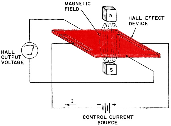
Fig. 1 - Control current and the magnetic field interact to generate a voltage between opposite edges of a Hall crystal.
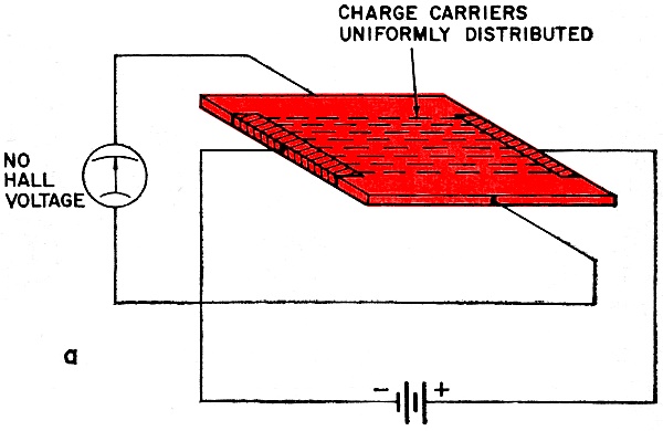
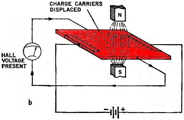
Fig. 2-a - Outside a magnetic field, charge carriers are uniformly distributed in the Hall element and voltage is zero.
Fig. 3 - Basic setup for measuring magnetic field strength with Hall device. As battery ages, R2 regulates current.
Fig. 4 - Hall-effect wattmeter responds to frequencies over a wide range.
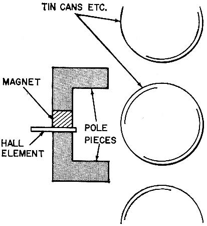
Fig. 5 - Sensitive to changes in magnetic flux, the Hall device is useful for counting ferrous objects such as beer cans.
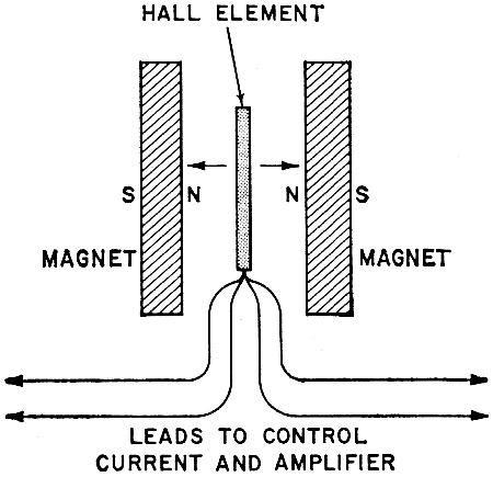
Fig. 6 - Minute movements of Hall device or magnets can be detected and measured.
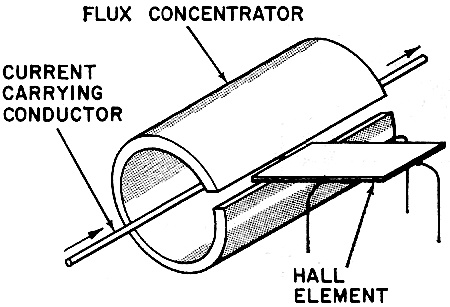
Fig. 7 - Magnetic field around conductor (or ion beam, see "Some Commercial Applications") is concentrated on Hall device and the output is measured as current.
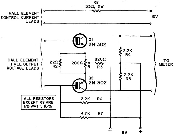
Fig. 8 - Low output voltage from Hall-effect element can be amplified with this differential amplifier circuit.
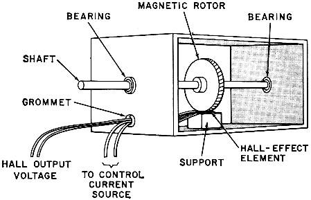
Fig. 9 - Magnetic rotor supported on freely rotating shaft changes polarity and output amplitude of nearby Hall element. Setup can be used to sense direction or indicate speed.
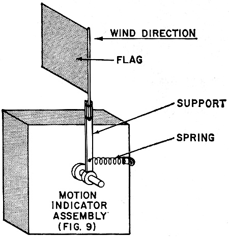
Fig. 10 - Using the shaft-position indicator (Fig. 9) to show wind velocity.
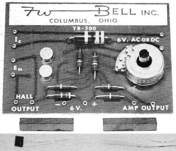
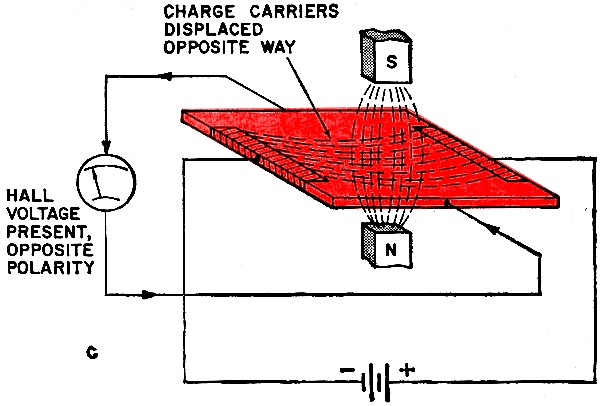
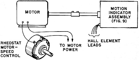
Fig. 11 - Spinning shaft in Fig. 9 generates alternating voltage. Figure 1 gives an idea of the basic Hall-effect concept. The Hall-effect device proper is fabricated from a thin slice of semiconductor material to which are attached suitable electrodes and conducting leads. This assembly is encapsulated in a protective coating to protect it from contamination. As shown, the Hall-effect device has four leads. Two are connected to the control-current source, while the other two leads deliver the Hall voltage. When the Hall-effect device is placed in a magnetic field and the control current is applied to it, a voltage appears across its Hall-voltage terminals. The amount of Hall voltage developed is directly proportional to the intensity of the magnetic field and the amplitude of the control current. For example, if the magnetic field intensity is doubled while holding the control current at a constant value, the Hall output voltage will double. Similarly, the Hall output voltage will double if the value of control current is doubled while the magnetic field strength is held constant. Doubling both the magnetic field intensity and control current, the Hall voltage will increase four times, the Hall voltage thus being a product of the magnetic field and control current. To see more clearly how a Hall-effect device works, let's take a look at Fig. 2, which gives us an "X-ray view" of Hall-effect operation. In Fig. 2-a, no magnetic field is applied to the Hall-effect device. Under these conditions, the control current passing through it causes a flow of charge carriers, either electrons or holes, down the length of the device. Since no charge carriers collect at the edges of the Hall-effect device, no Hall voltage is developed. A magnetic field perpendicular to plane of the Hall element (b) deflects charge carriers, producing a potential difference between opposite edges. When the magnetic poles are reversed, the polarity of voltages generated are reversed. In Fig. 2-b, the setup is the same except that a magnetic field is applied. Notice that the charge carriers are now deflected so that they strike one edge of the Hall-effect device. This causes a difference in potential between its two edges. If we now reverse the polarity of the magnetic field (north pole for south pole and vice versa) the charge carriers will be deflected in the opposite direction, as shown in Fig. 2-c. This will reverse the polarity of the Hall output voltage. A good analogy of this deflection of charge carriers is the cathode-ray tube, in which a beam of electrons is deflected by a magnetic field within the tube. The Hall output voltage obtainable from a typical Hall-effect device is small - in the neighborhood of 100 millivolts or so with a magnetic field strength of 1000 gauss. Therefore, it is generally necessary to amplify the Hall output voltage. Now that you are aware of what the Hall-effect device is and how it operates, just what is it good for? Perhaps its most obvious application is in the measurement of magnetic field intensity. Fig. 3 shows a simple arrangement for this. The Hall-effect element is supplied with its rated control current by the battery. Potentiometer R1 is adjusted to supply the rated control current while current regulator R2 maintains a constant value of control current as the battery ages. The Hall-voltage output signal is applied to a direct-coupled amplifier, which amplifies the signal and applies it to a calibrated meter. The direct-coupled amplifier is generally a balanced (differential) type, so that in the absence of a magnetic field the slight residual Hall voltage can be zeroed out, and the meter will be deflected only when the Hall-effect device is in a magnetic field. There are, of course, more complicated Hall-effect magnetic-field measuring arrangements, but the basic principle just described is generally followed. The Hall-effect wattmeter is another Hall-effect device. The Hall-effect wattmeter has an advantage over conventional direct electromagnetic-movement type wattmeters in that it will respond equally well to a much wider range of frequencies (for example, 10 to 100,000 Hz). Fig. 4 shows the basic arrangement of the Hall-effect wattmeter. As you can see, the Hall-effect device is placed between the pole pieces of an electromagnet whose winding is in series with the load to which the wattmeter is connected. The Hall-effect element's control current is derived directly from the supply voltage through a current-limiting resistor. By this hookup, the element's control current is proportional to the supply voltage while the magnetic field applied to the element is proportional to the load current. Since the Hall output is the product of the applied magnetic-field intensity and control-current intensity, its value indicates the power consumed by the load: power = voltage X current. Metal Detector Figure 5 shows how the Hall effect may be applied to detect ferrous (iron and steel) objects. This type of metal detector, while sensitive only within about an inch, is nevertheless very useful as a ferrous-object counter, etc. It responds to both stationary and moving ferrous objects and, unlike photocell detectors, can operate in cloudy atmospheres which would disable photocell systems. As you can see from Fig. 5, the Hall-effect element is mounted with a permanent magnet in a small U-shaped assembly. When a ferrous object comes close to the open ends of the U, it shortens the magnetic path between the ends of the U. As a result the magnetic field applied to the Hall element is increased. This in turn produces a larger Hall output voltage, which is amplified and can then be used to energize a relay or as a electromechanical counter. The Hall effect can also be used to measure extremely small mechanical movements. As shown in Fig. 6, the Hall-effect element is mounted midway between two small permanent bar magnets. In this position, there is minimum Hall output voltage from the element, because magnetic fields of equal strength and the same polarity (north-north) are on each side of the Hall element. If the Hall element is displaced to one side, there will be a stronger magnetic field on one side of the Hall element and a Hall output voltage will be generated. If the element is moved to the opposite side of center, a Hall output voltage will also be generated, but of opposite polarity. Thus, this arrangement will register the amount and the sense of the movement. As shown in Fig. 7, the Hall effect can also be used for current measurement. As you know, any conductor carrying an electric current has a magnetic field around it. The intensity of the field is proportional to the current strength. By placing the Hall element in the gap of a flux concentrator (a device which concentrates a magnetic field into a small area) placed around the conductor, the conductor's magnetic field will be applied to the (north-north) are on each side of the Hall element. The Hall output voltage will be proportional to the strength of the magnetic field around the conductor, which, in turn, is proportional to the current flowing through the conductor. The Hall output voltage is amplified and applied to a meter calibrated in amperes or milliamperes. There are other useful applications for the Hall-effect, but the ones we've mentioned are probably the most common. Experimenting with the Hall Effect Now that you have a good understanding of the Hall effect and how it is used, you might like to try putting it to practical use. You will need a Hall-effect element. An inexpensive source is the F. W. Bell Co., 1356 Norton Ave., Columbus, Ohio 43212. I used one of Bell's BH-700 Hall-effect elements in all the following experiments. It is available direct from the manufacturer for $10.75. To boost the low Hall output voltage obtained from the Hall-effect element, a dc amplifier is required. There are, of course, a number of circuits that can do the job, and the simple differential (balanced) transistor amplifier shown in Fig. 8 will do the job nicely. This circuit is identical to that of the completely packaged printed-circuit amplifier available from the F. W. Bell Co. as part of their Hall Pak Kit. The kit, available for $21.95, also contains one BH-700 element, two small bar magnets and an instruction booklet with applications. The amplifier can be powered by a 9-volt transistor-radio battery, with a 6-volt lantern battery supplying the Hall control current. The output of the amplifier can be applied to either a vtvm with a low range of 5 volts or less, or to a 100-μA meter. Now, on to the experiments. Measuring Magnetic Field Strength With the element, batteries and amplifier connected as shown in Fig. 8, apply power to the amplifier and control current to the Hall element. With no magnetic materials near the Hall element, adjust the amplifier's balance control, R1, for a mid-scale meter reading. Bring a small permanent magnet near the Hall element. The meter deflects, indicating the presence of a Hall output voltage from the element. As the magnet is moved closer to or farther from the Hall element, the Hall output voltage will vary proportionally, as indicated by the meter. Notice that the direction of meter movement is determined by the polarity of the magnetic field. A Noncontacting Position Indicator Here's a Hall effect project for which you can find a number of applications. Basically a direction-sensing rotational-motion indicator, it can be used as a wind-speed indicator, a liquid-level indicator, for "electronic scales," or as a source of low-frequency ac signals, to name but a few. Figure 9 shows the setup. A small permanent-magnet rotor (type DM- 662, Dura Magnetics, 5354 Whitford Rd., Sylvania, Ohio, 43560; $1.45) is mounted on a shaft supported between two panel bearings so that it rotates freely when the extended portion of the shaft is turned. A BH-700 Hall-effect element is mounted approximately 1/16" from the edge of the rotor, as shown in Fig. 9. When the shaft is rotated, the rotor edge moves past the Hall element, generating a Hall output voltage proportional to the magnetic field intensity at the edge of the rotor. The Hall output voltage will vary from a maximum negative value, decrease to zero, then rise to a maximum positive value. The polarity and amplitude of the Hall out-put voltage will depend on the position of the shaft. This arrangement is better than devices such as a potentiometer-type position indicator, because there is no wiper to wear down a wire or carbon resistance element. Also, there is less friction on the rotating shaft and less torque is required to turn it. Now let's put our little gadget to several practical uses. Fig. 10 shows the position indicator as a wind-speed gage. The shaft of the indicator is fitted with a small clamp to which is attached a metal flag. A spring is attached to the bottom of the flag support. The spring returns the flag to its rest position when no pressure is applied to the flag. Spring tension is adjusted so that the rotor is turned approximately 45° when there is maximum wind pressure. The differential amplifier is connected to the Hall output-voltage leads of the element. With power applied to the amplifier, its balance control, R1, is adjusted for a zero meter reading when the flag is at rest. Moving the flag with a finger should cause the meter to read upscale. If the meter reads backward, simply reverse its leads for correct polarity. To calibrate the meter scale, take it to a clear spot outdoors. Check with your local weather bureau to obtain the current wind speed, and ad-just the indicator's spring tension to get an appropriate meter reading. By "appropriate," I mean a half-scale meter reading for a 50-mph wind, quarter-scale reading for 25 mph, or less for lower velocities. Figure 11 shows how the position indicators can be used to furnish low-frequency ac signals from less than 1/60 cycle per second upwards to 100 Hz or more. The shaft of the position indicator is coupled to the shaft of a small, variable-speed motor. The speed of the motor is controlled by rheostat R, and the Hall output-voltage leads from the Hall-effect element are connected to an amplifier. As the motor spins the rotor past the Hall-effect element, a Hall output voltage is generated. It will vary in accordance with the varyingly magnetized edge of the rotor as it passes by the element. The rate of these variations is determined by the speed of the rotor, which, in turn, is governed by the motor speed. From here, you're on your own. The number of applications for Hall-effect elements seems to be limited only by imagination. So dig in! R-E Some Commercial Applications of Hall-Effect Devices
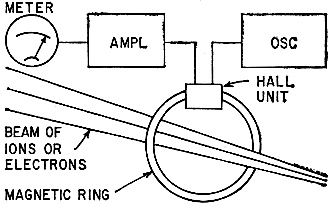
A simple and handy device for measuring small direct currents is sketched in the diagram. A small magnetic core is arranged around the current carrier, and the Hall unit is inserted in an air gap. When the dc input to the Hall crystal is supplied by a small battery, it is possible to measure currents down to 100 mA without amplification. With an amplifier, currents as small as 5 mA, such as ion- and electron-beam currents, can be measured. If the Hall crystal is placed in a waveguide so that the electric field is parallel to its surface and the magnetic field is perpendicular to it, the output of the Hall unit will be proportional to the magnetic field strength. This output can be amplified and used to drive a wattmeter calibrated to read microwave power.
Posted September 5, 2023 |
|
 The measurement of magnetic field strength with
Hall generators (crystals) can be carried out with a number of measuring instruments
of different sensitivities. One typical magnetic-field-strength meter is the Magnatest
Hall Effect Instrument. It can be used for field measurements on magnet systems,
measuring magnetic leakage flux, nondestructive material testing, and determining
the magnetic behavior of individual grains of various orientations in transformer
core materials.
The measurement of magnetic field strength with
Hall generators (crystals) can be carried out with a number of measuring instruments
of different sensitivities. One typical magnetic-field-strength meter is the Magnatest
Hall Effect Instrument. It can be used for field measurements on magnet systems,
measuring magnetic leakage flux, nondestructive material testing, and determining
the magnetic behavior of individual grains of various orientations in transformer
core materials.