Electronic Counter Tube - Mullard E1T
|
|
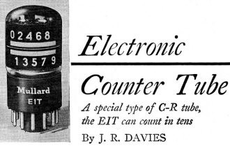
If you look up "bit" on Wikipedia, is claims the word is a portmanteau of binary + digit, but according to the "Electronic Counter Tube" article in the March 1956 issue of Radio−Electronics magazine, it comes from binary + unit. The cited reference is a 1980 book. That's a minor point, but I wonder if the belief has changed over time. Going further down the metaphorical rabbit hole, per the same source, "The term byte was coined by Werner Buchholz in June 1956, during the early design phase for the IBM Stretch computer." Now, back to the topic at hand. The E1T "Decade Counter Tube" was produced by Mullard, located in the UK. It had an ingenious design which directed an internal electron beam onto fluorescent numerical segments according to the number of pulses supplied to the increment grid (D1 in Fig. 1). A holding voltage was not needed to maintain the position of the last pulse. Pulse shape was critical, and was supplied by a special-purpose tube, the Mullard E90CC. Electronic Counter Tube
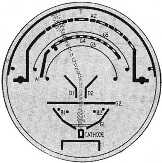
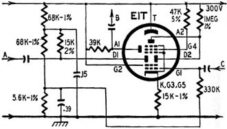
By J. R. Davies One of the most fascinating branches of electronics is that of counters and computers. Devices of this type, with their phenomenal speed and accuracy, appear to the layman to be somewhat of a near-miracle. To describe some of the more advanced computers as "electronic brains" is not too far from the truth - such equipment, in their special use, simulate functions of the human brain very closely. The basic "cell" of most conventional counters and computers is the vacuum tube, usually working in what are known as binary units, or "bits." The reason for this choice of units is that a single tube can be relied upon only to indicate one of two states: when it is conductive (passing cathode current); when it is nonconductive (beyond grid cutoff). It would be impracticable to expect a tube to cope reliably with three states such as: off (past grid cutoff); half-on (low cathode current); fully on (high cathode current). Tube spread and deterioration could cause the half-on and fully on states to lie too close together after a period of use, and there would be a risk of misinterpretation. Fig. 1 - Internal construction of E1T. Fig. 2 - Schematic of a typical circuit in which the E1T may be used. A tube capable of counting in 10's or decades would overcome this trouble. This type of tube exists, a typical one being the E1T made by Mullard in England. This tube may be used in cascade with others with the result that when one tube has reached what would otherwise be "10" it triggers the next tube in the circuit and slips back itself to zero. Thus, a group of three tubes can be used to count to 999: the first tube counts digits and triggers the second tube at every decade; the second tube counts in 10's and similarly triggers the third tube which counts in 100's. To add to its versatility, each of the E1T tubes not only counts but also indicates its number on an easily read built-in fluorescent screen. The photo shows the tube and its indicating screen. The top counting speed is 30 kc. Construction and circuitry The internal construction of the E1T is shown in Fig. 1. Fig. 2 illustrates a typical circuit. In Fig. 1 the cathode emits an electron stream which passes through grid G1 and the beam-forming electrodes B1, B2. The stream next passes through G2 and, being at B-plus potential, is accelerated. Leaving G2 the electron stream is in the form of a thin ribbon-shaped beam, the major width of the ribbon being at right angles to the surface of the paper. The beam now travels through deflector plates D1, D2 to G4. However, G4 is perforated and the narrow beam is not wide enough to pass through more than one of its 10 apertures before it reaches segmented plate A2. This plate has apertures also and the beam has to pass through one of these before it finally strikes fluorescent conductive target T. The apertures in A2 are staggered alternately, thus allowing the fluorescent indications on the target to be similarly staggered for well spaced out readings. In addition, A2 is sectionalized, preventing the beam from spreading too widely after it has passed through the particular aperture it has chosen in G4. Due to the narrowness of the beam, once it has settled at a particular aperture in G4, it remains locked there until some external force is applied to move it elsewhere. Deflector plates D1 and D2 are arranged so that they provide this beam-moving force in a horizontal plane relative to the surface of the paper in Fig. 1. Plate D2 has a positive potential higher than that on D1. Thus the beam is attracted, when the tube is first switched on, to the furthermost right-hand aperture of G4. This position corresponds to 0 on the fluorescent target. When a positive counting pulse of the correct shape (provided by a suitable input filter) is injected into the circuit of Fig. 2 at A, D1 becomes momentarily more positive than D2 causing the beam to move to the left. However, the shape of the pulse is such that the beam moves only one step (or one aperture in G4) whereupon it then stops and becomes locked in its new position. Successive pulses cause the beam to move to successive apertures. On the arrival of the tenth pulse, the beam passes from the tenth aperture of G4 and strikes A1. Current is drawn by this plate, causing a negative pulse to appear at point B (Fig. 2). This negative pulse triggers an external circuit which does two things: it applies a reset pulse to the tube so that it may return to zero; it passes a counting pulse to the next decade-counting tube along the line. The reset pulse consists of a negative pulse injected at C and causes G1 to go negative, whereupon the tube cuts off altogether. When the negative pulse at G1 ceases, the counting cycle starts up all over again with the electron beam of the tube passing through the furthermost right-hand aperture in G4. The tube is then ready to count another decade.
Posted October 17, 2022 |
|


