The RCA Antennalyzer
|
|
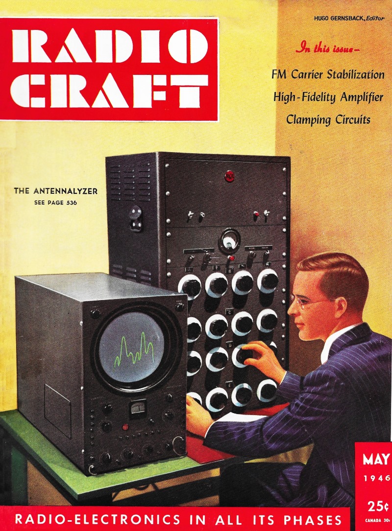
It is little wonder that advancements in technology, mathematics, finance, medicine, chemistry, and other disciplines requiring massive numerical computation began accelerating at a rapid pace following the invention of computers. The mechanical computers of Blaise Pascal and Charles Babbage were some of the earliest attempts to make laborious, repetitious calculations faster and less error prone, and they quickly led to many other types of general- and special-purpose machines that by the mid-twentieth century were calculating ballistic flight paths, astronomical positions, electrical circuit functions, probabilities, and other quantities. Programmable electronics computers like the ENIAC greatly enhanced the ability to apply mathematics to just about any problem. However, even by the early Apollo era the government and private institutions employed teams of human calculators to crank out large volumes of tabular data for applications too complex for many computers due to the functions and precision required. It was not until the advent of semiconductor microprocessors and solid state memory that things really got moving. This 1946 issue of Radio-Craft magazine reported on the RCA (Radio Corporation of America) "Antennalyzer" contraption (a form of analog computer) that, via an array of hand-adjusted potentiometers, was able to predict the radiation patterns of a multi-element phased array. Through the use of clever electronic design, a representation of the resulting radiation pattern was displayed on an oscilloscope (in either rectangular or polar coordinates) so the skilled designer had immediate feedback from his actions. He could either set in specific known values and observe the resulting pattern, or conversely he could adjust the display to the desired pattern and then read the corresponding values off the dials. Of course the settings were only accurate for a narrow bandwidth, so many iterations would be required for a broadband array. The RCA Antennalyzer - Electronic means of designing directional antennas
The march toward higher frequencies has accentuated the need for and increased the possibility of using directional antennas. As frequency is increased, it becomes more and more difficult to generate large amounts of power. The difficulties inherent in the construction of antenna systems, however, decrease as dimensions are reduced. An antenna system which, at broadcast frequencies, would cover several acres of ground and require tons of copper, may be mounted on a single light mast if the frequency is high enough.
The Antennalyzer obviates problems like this. Equations for the radiation patterns of directional antenna systems are well known, but the arithmetical work necessary to. secure the plot of a radiation pattern is tedious and time-consuming. It is not surprising that efforts have been made to do this work mechanically and even electrically. As early as 1943 an electrical system for calculating the polar diagrams of systems with as many as five aerials was described (Electrical Communications, Vol. 21, No. 2, abstracted in Radio-Craft August, 1943). This was non-electronic in action, using a number of Selsyns fixed on a shaft, their phase position simulating that of the separate aerials in the antenna system studied. Rotating the whole group with the shaft is equivalent to taking measurements in a circle of azimuth around an actual antenna system, the "radiation pattern" being read on an a.c. voltmeter and plotted every few degrees around the circle. Electronic Means Sought It was not surprising that engineers began to cast about for electronic means of handling these complicated calculations, only incomplete solutions of which could be approximated with earlier and cruder apparatus. The RCA Antennalyzer was developed to perform the major part of this work entirely by electrical means with no moving parts except the series of potentiometers which change the various parameters. Through its use, the time required to solve an antenna problem has been reduced from several days to a few hours. Fifty-two tubes are used to perform the various functions. Developed specifically for the design of directional antennas for broadcast use, the Antennalyzer, in the form illustrated on the cover, will yield the radiation pattern of directional antennas which have as many as five towers or sources of radiation. Each source is characterized by four parameters: 1, the distance from a reference point; 2, the azimuth angle with respect to a base line; 3, the amount of current in the antenna, and 4, the phase angle of this antenna current. Thus the Antennalyzer has four potentiometers associated with each antenna; with one exception. One antenna is located at the reference point and carries unit current at zero phase. Hence no controls are required with this antenna. The radiation pattern is displayed directly on the face of the cathode-ray tube, either in polar or rectangular coordinates. The Antenna may be used in two ways. The dials may be set to correspond to a given antenna configuration after which the resulting pattern is observed on the C-R tube, or, when a given pattern is the goal, the dials may be twiddled until the proper pattern is obtained. Then the dial settings are recorded. These dial settings tell where, to. locate the powers, as well as the current ratios and phase angles to use. With a little practice, this operation may be performed in a few minutes. Metering devices are included in ,the Antennalyzer so that the ratio of maximum field intensity to. r.m.s. field intensity is obtained. One interesting point in connection with the use of the Antennalyzer was observed recently. After engineers familiar with the operation of the instrument had established the proper location for an antenna array, the final trace was marked with crayon on the C-R tube face. Then the controls were misadjusted and the Antennalyzer turned over to an engineer who had never used the device. In six minutes he had manipulated the dials until his trace on the oscilloscope coincided with the crayon markings. Checking his dial settings with those first recorded, it was found that he had arrived at an antenna arrangement which differed from the original. This can happen under certain circumstances. It has been found that when a rather complicated pattern is desired, where the use of three or more antennas are necessary, it is possible to find two or three configurations which yield the same pattern. Measuring Antenna Gain One of the uses of the Antennalyzer is in measuring the gain of a directional antenna system. When the designer has arrived at the proper pattern he usually desires a knowledge of the scale factor to place on the plot. An exact determination involves a knowledge of the mutual resistance existing between the antennas. However, an approximate answer may, be obtained quickly by plotting the pattern in polar coordinates and measuring the area with a planimeter. A circle whose area is the same is then taken as the circle from a single antenna operated with the same power. The radius of this circle is the r.m.s. value of the horizontal polar diagram. This approximate relation may be obtained by measuring the peak value of the signal coming out of the Antenn-lyzer and then measuring the r.m.s. value of the same signal. The instrument panel used for this purpose may be seen near the top of the Antennalyzer. The signal from the Antennalyzer is fed first to the peak-reading voltmeter which consists essentially of a diode rectifier. The input signal is adjusted until the meter in the output reads full scale. Then the signal is switched to the input of the r.m.s. voltmeter. The output meter is switched to this voltmeter at the same time. Since the meter scale is calibrated with full scale equal to unity, the new reading is now the ratio of the r.m.s. signal to the peak signal.
Posted May 4, 2021 |
|