Short-Cuts in Radio
|
|
First prize in this circa 1936 reader-submitted design ideas went to William G. Scott for his wind-powered battery recharger. It was a rather elaborate contraption made of surplus lawn mower and automobile (Ford Model T, no less) generators. There are two very good reasons why someone would find the need to build his own battery charger in the era. First, good luck finding a commercial product to do the job, and if you could, the cost would be prohibitive for most radio enthusiasts. Second, prior to the Rural Electrification Act of 1936 (which took many years to fully implement), most households not in or near cities and towns had no commercial electric service. Electricity, if any, was supplied by deep cycle storage batteries for powering radios, electric lights (as opposed to kerosene or gas lights), kitchen appliances, etc. Many farms had windmills that did double duty of pumping ground water and driving a generator. BTW, a $10 prize in 1936 is, according to the BLS' Inflation Calculator, the equivalent of $219 in 2023 money. See also "Short-Cuts in Radio" from the June 1936 issue of Radio-Craft. Short-Cuts in Radio First Prize ............ $10.00 Second Prize ........ $5.00 Third Prize .............. $5.00 Honorable Mention Experimenters: Three cash prizes will be awarded for time- and money-saving ideas. Honorable mention will be given for all other published items. Send in your best "kinks"!
Fig. 1 - A wind charger in which the main item is a discarded lawnmower. First Prize - $10.00 Homemade Wind Charger. A discarded lawn mower and an auto generator are the principle parts of this machine. The mower is dismantled and the frame removed. On one wheel, the shaft that revolves the blades is cut off leaving a stub of about 2 ins. The other end is cut so that the whole bearing of the cutter shaft is removed. The wheel that has the short shaft left on is mounted at right-angles to a board which is used as the base, as may be seen from Fig. 1. The short shaft is at the top and is connected to the generator shaft by a metal coupling. The generator, which in my case was a Ford model T type, is mounted on a frame of wood, and held by straps over the top: The wood is cut away a the rear so that the band over the brushes may be removed. The other wheel is used as the turntable and is bolted under the wood platform. It is a good idea to add a steel plate between the inner frame of the wheel and the pipe flange, as the metal is often not very thick at this point. The tail is of sheet metal bolted to the wooden platform. The propeller blades for my machine are of heavy sheet iron, each about 30 ins. long and 5 ins. wide, with a twist of about 45 deg. The cutout is left in place on the generator, one wire running from it to the positive of the battery and the other wire from the generator frame to the negative. The third brush is adjusted so that the charging rate is about 3 A. at normal speeds. A switch is connected so that at any time the generator is not to be used for charging it may be short-circuited. William G. Scott
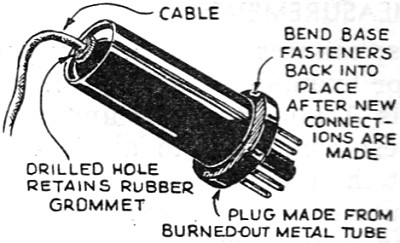
Fig. 2 - Plug made from metal tube. Second Prize - $5.00 Defective Metal Tubes Make Inexpensive Plugs. Defective or burned-out metal tubes make excellent equipment plugs. The 6H6 tubes are best for speaker plugs, while the 6C5, 6F6, and small 5Z4 tubes are best for analyzer plugs. First, bend the metal shell so that the base may be removed, after unsoldering the wire leads, as seen in Fig. 2. Then drill a hole in top and bottom of the tube and run a screwdriver through to clear the elements out of the way. The cable may then be pushed through and soldered to the base prongs, after which the base is again crimped in place. If shielded cable is used it may be soldered to the top of the tube; and if not, a rubber grommet should be inserted in the hole. W. A. Lynch
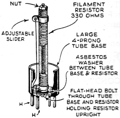
Fig. 3 - Ballast tube replacement. Third Prize - $5.00 Emergency Ballast Replacement. Many of the late midget and A.C.-D.C. sets have ballast tubes in place of the older line series resistors. These tubes are often hard to get in the correct value, and as the customer is always in a hurry for the set, I install the gadget shown in Fig. 3 until I can secure the correct replacement. This is simply a large wire-wound resistor bolted to a base from a 4-prong tube. The slider enables the resistance to be adjusted to take care of any receiver tube arrangement. If the set has a tap in the ballast tube for use with a pilot lamp, this is easily taken care of by an extra slider on the resistor. Robert Owens Honorable Mention
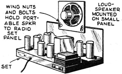
Fig. 4 - One speaker on several sets. Moveable Speaker. When you have several receivers and only one speaker, you can save both time and money by use of the scheme shown in Fig. 4. Mount the speaker on a piece of wood, and drill holes in the lower corners. Then drill holes in the panel of each set and insert bolts through them so that the speaker baffle may be fitted to any one. Using a plug-in cord and wing nuts, the speaker may be changed in a hurry. Edward Snow Honorable Mention
Fig. 5 - Plate-bending pliers. Easily -Made Aligning Tool. To prevent body capacity when adjusting the slotted plates of gang condensers, the scheme shown in Fig. 5 is handy. File 2 small depressions in the jaws of the pliers and cement-in strips of good insulating material such as hard fibre or Bakelite. Peter Luciw Honorable Mention
Fig. 6 - Grounding A.C.-D.C. sets. Quieting A.C.-D.C. Sets. Because of the circuit used in the midget sets it is not usual to provide a ground wire. In some localities these receivers pick up lots of man-made static. By using a condenser as shown in Fig. 6, the receiver is efficiently grounded and the volume is very noticeably increased in all cases. The dual condenser must be of the paper type as the electrolytics heat up on A.C. Be sure to put the condenser on the house side of the fuse box. I now use this stunt in my shop which is right next to a theatre that produces lots of noise, and it clears up the noise and doubles the daytime reception range! Wilbur C. Redwine Honorable Mention
Fig. 7 - Stuck pulley remedy. "Stuck Pulley" Remedy. When the pulley of my pole jammed after I had lowered the antenna to make repairs. I was at a loss as to how it could be removed. The pole is 65 ft. high and too large to be taken down, yet too small to climb. The problem was solved as depicted in Fig. 7. L. Wright Honorable Mention
Fig. 8 - Substitute microphone. Efficient Microphone - an old idea brought up-to-date. I find that a really good substitute mike is a permanent-magnet type dynamic speaker. It is connected as shown in Fig. 8, using the output transformer connected in the high-impedance position, which latter may be found by reference to the chart furnished for the universal output transformer on these speakers. Frank Shoemaker Honorable Mention
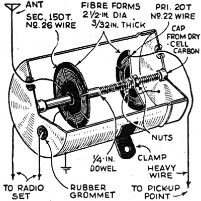
Fig. 9 - Auto noise eliminator. "Balancing Out" Type of Noise Eliminator. The price of a set of suppressors may be saved by the use of this simple device. As seen in Fig. 9, it consists mainly of 2 coils wound on ibre forms. These are mounted on a 1/4-in. wood dowel, one being fastened with cement, and the other held with 2 nuts. The rod is threaded by screwing the nuts on. The large coil is connected in series with the antenna lead of the receiver. The other coil is grounded at one end and the other end run to some pick-up point in the engine compartment (the radiator tie-rods are a good spot). Robert Van Houten Honorable Mention
Fig. 10 - Neon output indicator. Sensitive Neon Indicator. Neon lamps make very cheap output indicators, but they require a higher voltage to "strike" them than is available in certain cases where the set input must be kept low while testing. A Ford model T spark coil may be connected as shown in Fig. 10, and will step up the weak impulses so that a good indication is obtained from the lamp. E. J. Kujanik Honorable Mention
Fig. 11 - P.A. volume indicator. Volume Indicator. A neon lamp makes a valuable indicator for use on a P.A. amplifier. It has the advantage of being visible from practically any point in the hall or grounds where the system is installed. The lamp is hooked in the output circuit of the power amplifier, in series with suitable resistors. The size of the lamp is not critical, but the smaller the lamp, the larger the resistors used with it. Silas R. Perkins
Posted December 27, 2023 |
|