New Radio-Electronic Patents
|
|
It has been three or four decades since I have seen anything about a Lecher Line, the last time in memory being in a college lab. It might have been a physics lab, but most probably an EE lab. We used one to measure wavelengths of signals from an RF generator. The apparatus looked sort of like the one in the Wikipedia link, only just a little more modern (but not much more, being typical school equipment). This new patents report from a 1947 issue of Radio-Craft magazine has a waveguide version of a Lecher Line that supposedly was able to do more precise measurements of very short wavelengths by providing for detecting the internal wave over multiple wavelengths instead of just a single half wavelength. It was developed at Bell Telephone Laboratories, so undoubtedly it was a quality instrument. The other patent covered was an AM-FM detector circuit which boasts a novel method of switching between AM and FM detection by a simple change in tube plate bias. Links to the patents are provided below. New Radio-Electronic Patents By I. Queen Precise Lecher Measurements Patent
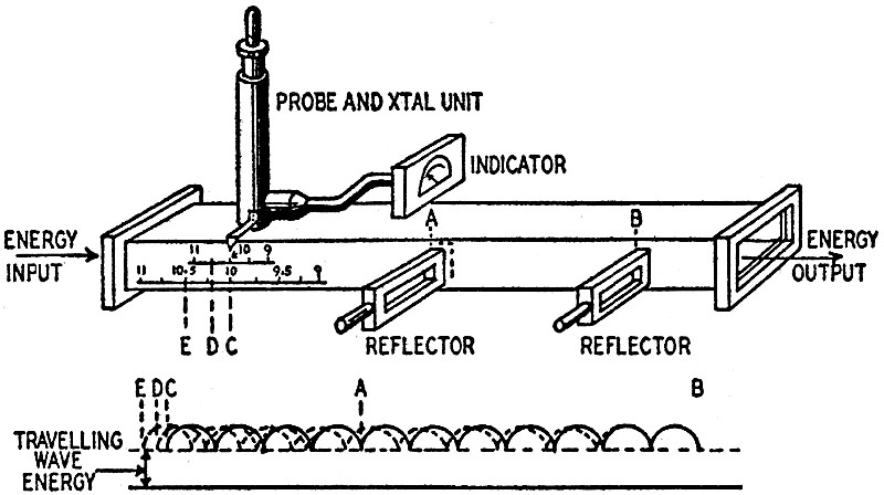
Glenn R. Frantz, Pt. Washington, N. Y. Allen F. Pomeroy, Bernardsville, N. J. (assigned to Bell Telephone Laboratories, Inc.) Patent No. 2,419,208 Low wavelengths are conveniently measured by Lecher Wires. The r.f. current is introduced along a transmission line which is shorted at some point. A detector is connected across the line and its distance from the short is varied until it shows a voltage node. The detector is moved further along the line until another node is indicated. The distance between consecutive nodes equals 1/2 wavelength. For very short wavelengths, a wave guide is used instead of a transmission line. The detector is coupled to a probe inserted into the guide. The relative error of a measurement of length increases at short lengths. This invention reduces the error by measuring over a distance of several wavelengths. As shown, 2 reflectors are used to short-circuit the guide. The distance between them is equal to any number of half-wavelengths at the average or median wavelength which it is proposed to measure. Each reflector is equipped with a handle so that it may be inserted or withdrawn from the guide. The probe is movable over a limited distance, the position being measured by calibrated scales. To make a measurement of wavelength, v.h.f. energy is introduced into the guide, and the reflector A is inserted. If the wavelength equals the average or medium value for which the equipment is calibrated, the probe will pick up no voltage at C, exactly 4 half-wavelengths from A. At this point the scales indicate the average wavelength of the equipment. If the wavelength is higher, the probe must be moved back, say to D, to obtain a null. The length CD is 4 limes the change of wavelength. The new wavelength is read on the upper scale. For still higher precision, A is withdrawn and B inserted. Now the probe must be moved back to E for a minimum pickup. CE equals 11 times the change in wavelength because this reflector is 11 half-wavelengths from C. The lower scale is now observed for actual wavelength. It is clear that this scale will have more widely spaced and readable calibrations due to the fact that the actual wavelength change has been multiplied by 11 instead of 4. Still greater precision is obtainable by placing a reflector still further from the probe.
FM-AM Detector Patent
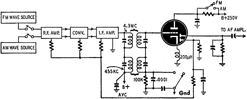
Frederick C. Everitt, Brecksville, Ohio (assigned to Radio Corp. of America) Patent No. 2,422,087 Both FM and AM have advantages of their own and several manufacturers are now selling receivers which can be switched to pick up either type of broadcast. Each requires a different band width and a different intermediate frequency. so there must be two separate i.f. channels. This patent discloses a single detector stage which can be used on both, however. Output from the two i.f. channels are combined and connected across two i.f. transformers in series. One is tuned to the 4.3 mc FM channel and the other to the 455 kc AM channel. Each transformer has negligible impedance at the frequency of the other, so it is not necessary to switch or short one out while the other is effective. When the 2 switches are in the FM position (as shown) the plate voltage is dropped to about 25 by the plate resistor, and at the same time an R-C network is placed in the grid circuit. Therefore the triode acts as a limiter. When the switches are thrown to AM, the grid network is shorted out and the plate voltage is returned to normal (250 volts). The tube is then a class-A amplifier. The detector circuit is rather unconventional. The cathode coil has an inductance of about 200 µh and a natural frequency of 4.2 mc. Its reactance varies with frequency when FM broadcasts are being picked up. The deviations from the center frequency of 4.3 mc. are thus translated into amplitude changes of voltage on the cathode. Since the two diode plates are normally at ground potential, the potential (with respect to the cathode) changes in the same way. Currents therefore flow through the diode resistors. One diode is used as a detector, the other as a.v.c. supply. An important advantage of this system is that there is no loading of the i.f. transformer secondaries when AM broadcasts are received. The grid circuit does not carry current. This gives better selectivity and sensitivity. On the other hand, the triode produces no gain since its load is in the cathode circuit. November 13, 2020 Update: The following note was received from RF Cafe visitor B.B. "Hi Kirt, Re your article on the Lecher line - I used one in a college RF lab also. All the lab students seemed to have trouble getting anything close to the predicted results when measuring along the line when it was loaded with anything other than the nominal line impedance (600 ohm?), or something that put a reflection on the line, stubs, whatever. Looking at the setup, the sources for the lines were donated 50 ohm signal generators. These were attached directly to the line with no matching network. Not even a balun. Therein was the source of the problem - the initial reflection caused by non-nominal loads was being re-reflected by the mismatched source impedance and summing with the initial reflection at the measurement point (and being reflected again...). I talked to the prof about it, even gave him a paper I wrote on it with calculations. (He was all about the math). As expected, he never did anything about it. Wouldn't it have been nice for the students if their measured results had come close to the predicted values?"
Posted November 12, 2020 |
|