Radar Principles (Part 1)
|
||||
This is the first of a two-part "Radar Principles" article by British engineer and researcher Dr. R.L. Smith-Rose. Dr. Smith-Rose explains the basics of radio detection and ranging using simple illustrations and calculation examples. When these articles were written, radar had recently been credited with playing a major role in helping the Allies successfully wage war against aggressive Axis powers that were ravaging London and other European cities with air attacks comprised of both manned and unmanned vehicles. While the principles of radar were somewhat familiar to people because of its analogy to using hearing to estimate distance and location, the actual science behind the operation of radar was and still is considered a form of black magic nearly everyone. "Radar Principles - Part 2" appeared in the May 1945 edition of Radio-Craft. Radar Principles - Part 1 Part 1 - By R. L. Smith-Rose, D.Sc., Ph.D., M.I.E.E., F.I.R.E. *
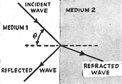
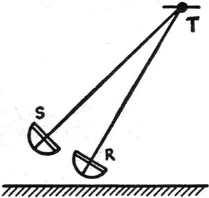
Radiolocation or Radar may be described as the art of using radio waves for the detection and location of an object, fixed or moving, by the aid of the difference of its electrical properties from those of the medium adjacent to or surrounding it. An intrinsic feature of the art is that no cooperation whatsoever is required of the object being detected. It is in this particular sense that radiolocation, as it was formerly known, differs from the long-established practice of radio direction-finding. The technique of direction-finding is confined to the determination of the direction of a primary source of radio waves. The source of the radio waves may be on the one hand an illicit sending station, the position of which it is required to determine; on the other hand, it may be a friendly radio beacon transmitter for the use of ships or aircraft fitted with direction finders to assist the navigator in determining his own position. The new art of radiolocation, however, requires no such cooperation, on the part of the object under examination; the latter, be it aeroplane, ship, building or human being is merely required to reflect or scatter some of the radiation which reaches it from a radio transmitter forming part of the whole Radar installation. The detected object is thus merely a source of secondary radiation which results from its being illuminated, as it were, by the incident radiation from the primary sending station. With this definition of the subject with which we are concerned, we may now proceed to an explanation of the fundamental principles forming the basis of this new application of radio waves. When electric waves, of whatever length, impinge on the boundary separating two media of different electrical properties, the path of transmission of the waves is altered; some of the wave energy passes across the boundary, but in doing so its path is bent or refracted; another portion of the wave energy is turned back from the boundary and forms the reflected portion of the waves on the same side as the incident waves (see Fig. 1). The relative magnitudes of the reflected and refracted waves depend upon the electrical properties of the media on the two sides of the boundary, the angle of the incidence (θ in Fig. 1), and the frequency or wave length of the waves. If these quantities are known, the reflecting power of the surface of separation of the two media can be calculated; and in many practical cases, this calculation is made easier by the fact that the first medium is air under normal atmospheric conditions, when its electrical conductivity is very small and its dielectric constant is approximately unity. If the second medium is a sheet of copper, of which the conductivity is very high, nearly all the incident energy in the arriving waves will be reflected; this is the result of the re-radiation from the conduction currents set up in the copper sheet by the arriving waves. Alternatively, the same result will be obtained with radio waves if the second medium consists of fresh water; for although in this case the conductivity is low, its permittivity is high and thus strong dielectric currents will be set up, particularly at high radio frequencies. In the case of soil or earth, which has both a moderate conductivity and an intermediate value of permittivity, a portion only of the incident wave energy will be reflected, the remaining energy passing into the medium to form the refracted waves. From these considerations it is seen that reflection of radio waves is caused at a discontinuity or boundary between two media, and when waves in air strike a surface, which may be either a metallic conductor or an insulating medium, the waves are reflected in some degree by the surface. If this surface is smooth in the sense that it is free from irregularities of a size approaching the wave length then the reflection is of the specular type such as we meet with in light waves; and in such cases if the waves impinge normally on the surface, they will be reflected back along the original direction towards the source of the incident waves. If the surface is not sufficiently smooth the reflection will take place in various directions, or the incident waves are scattered, as it is termed; and in this case only a portion of the reflected or scattered energy is returned along the path of the incident waves. Light Wave Measurements It is thus easy to understand how light reflected from solid or liquid media enables us to see the existence of these objects, and Fig. 2 illustrates the manner in which a searchlight enables a target - aircraft or cloud - to be seen by an observer situated at R, who can then determine its bearing and angle of elevation. This is an art which is well known and has been practiced for a long time; but it suffers from one serious drawback; this simple combination of a searchlight and an observer does not enable the distance of the target to be determined. In order to make this valuable addition to the observation, it is necessary to interrupt or modulate the beam of light in such a way that the time of transit of the waves between the source and target and then, back to the receiver may be determined. This important addition to the technique of visual observation was actually made as long ago as 1849 by Fizeau in his classical experiments to measure the speed with which light waves travel. Fizeau used a mechanical method of measuring the time of transit of an interrupted beam of light over a return path about three or four miles long. At that time, the distance was accurately measured and so the velocity of the waves determined; but if, as is the case nowadays, a knowledge of the wave velocity is assumed, then the length of a path with a reflector at its end can be determined.
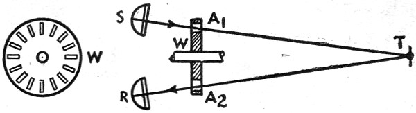
A possible arrangement of this method of determining the distance of a reflecting object by the aid of light waves is illustrated in Fig. 3. As before, light from a source S is transmitted to a target at T whence some of it is reflected back to a detector or receiver at R. In front of both Sand R rotates a disc or wheel W, with an even number of radial apertures in it, so that the beam of light is alternately interrupted and allowed to pass. With the disc stationary the outgoing and incoming beams pass through the corresponding slots at the end of a diameter. As the disc is rotated and its speed gradually increased, some of the light which has passed through a slot A, in front of S will be cut off, because by the time it has traversed A1-T-A2 the corresponding slot A2 will have moved round through a small angle. As the rate of rotation of the disc is increased, a speed will be reached at which the returning light will be cut off by the portion of the disc between the slots. As the speed of the disc is further raised the light will again be perceived at R, since while the light is traversing the path A1-T-A2 the disc will have rotated through an angle equal to that separating adjacent slots. Hence from an observation of the speed of the disc under these conditions, and assuming the velocity of the waves, the distance A1T can be determined. From this type of measurement and the associated observations of the angular directions of the reflector T in both the horizontal and vertical planes, the position of T in three-dimensional space becomes known. This, in essence, is the fundamental principle of radiolocation as it is practiced today. The writer is not aware to what extent, if at all, it became practicable to use it with light waves, but in any case, its use in this way would be severely limited to ranges normally detectable by the human eye under conditions of darkness and the occurrence of clear weather. Furthermore, in typical circumstances, the time intervals to be measured are very small - about 10 microseconds per mile - and the consequent practical problems involved in the rotation of the disc at the required speed are not easily solved. Electric Wave Reflections
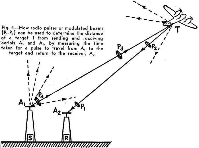
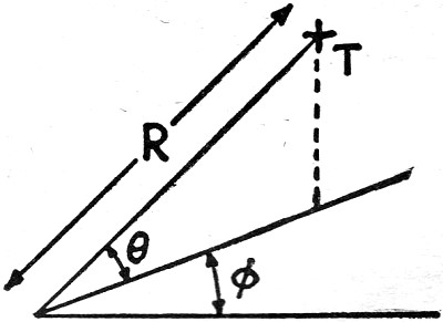
Radiolocation, or Radar, makes use of the longer electric waves in the radio-frequency portion of the spectrum. A complete station consists of a combination of a transmitter and receiver. The transmitting or sending portion emits radiation over a broad arc in the approximate direction it is desired to explore. When this radiation strikes an object having an appreciable conductivity or dielectric constant, some of the energy is reflected or scattered back towards the receiver which is installed moderately close to the transmitter. If the latter emits the radio waves in short trains or pulses, the time of transit of these to the reflecting target and back to the receiver can be measured, by displaying the received signals on the screen of a cathode-ray tube. The arrangement is indicated schematically in Fig. 4, where successive pulses P1, P2, P3, P4 have been emitted from the sending aerial A2 the first two pulses having already reached the target and been reflected back towards the receiving aerial A2. It is now required to determine the time of transit of anyone of the pulses over the path A1-T-A2. The pulses of radio-frequency oscillations arriving at the receiving aerial are suitably amplified and rectified, and then applied to the vertical deflecting plates of a cathode-ray tube. If the horizontal deflecting plates are connected to a suitable time-base circuit operating in synchronism with the pulse generating circuit in the transmitter, then for a fixed distance A1-T-A2, the received pulses will appear superimposed on one another as vertical deflections from the horizontal time-base. If furthermore. the time-base is made to start its deflection from the left-hand side of the screen at the same instant as the pulse of radiation leaves the sending aerial, then the distance along the time-base from its origin to the position of the pulse displayed on it is a measure of the length of path A1-T-A2. The type of picture obtained on the screen of the cathode-ray tube is illustrated in Fig. 5, in which the line OA represents the time-base which is locked to the transmitter in such a way that the length 0-T1 represents the time taken by an emitted pulse to arrive back at the receiver after reflection from a target T1. As we know that the velocity of radio waves is substantially 186,000 miles per second, the scale of the time-base can be graduated in miles, so that the distance of the target T1 is seen to be about 19 miles. A second received pulse is seen at T2 returned from another target at a range of about 35 miles. If one or both of these targets are moving, their changes in position are indicated by the movement of the pulses along the base-line on the screen of the cathode-ray tube towards or away from the point O. The amplitude of the pulse on the tube is proportional to the strength of the received signal, so that this naturally increases as the target from which the echo is returned approaches the receiver. When other conditions remain the same, the amplitude of the echo is also a measure to some extent of the reflecting properties of the target, for example, its size; and an experienced observer may be able to guess the nature of the target from the echo pulse seen on the tube screen. This measurement of the distance of the reflecting body responsible for the echo signals must be supplemented by a determination of the direction of arrival of the waves in both the horizontal and vertical planes, before the actual position of the reflector in space is completely known. These measurements can be made by well-established methods for observing the bearing or azimuth (θ in Fig. 6) and the angle of elevation above the horizontal (θ, Fig. 6). The first observation can be made by rotating the receiving aerial, which may at certain wave lengths be a horizontal dipole, about a vertical axis until the amplitude of the corresponding pulse decreases to zero; it is then known that the bearing is in line with the direction of the dipole. Alternatively, a pair of fixed aerials at right angles to one another can be used, connected to the field coils of a radio goniometer in the usual manner of a direction finder. Rotation of the search coil to the signal minimum position again enables the bearing to be determined. The angle of elevation of the arriving waves can be measured by comparing the amplitudes of the voltages induced in two similar aerials mounted one above the other at a known distance apart, depending upon the wave length in use and the range of angles of elevation it is desired to cover. This technique has been used for many years past by several investigators for measuring the angle of arrival of radio waves over long-distance communication paths, and it is directly applicable to the problem now under discussion. If the reflecting object being observed is an aircraft, then a knowledge of the range R and elevation θ (Fig. 6) enables the altitude at which the craft is flying to be determined. If the object of interest is a ship, then the angle of elevation is negligible, and the range and bearing determine its position. The above considerations all apply to the use of wave lengths of the order of, say, 5 to 50 meters, for which the dimensions of the aerials are such as to make it impracticable to obtain very concentrated beams of radiation by the use of local reflectors. If, however, much shorter wave lengths are used, then it becomes possible to arrange what is, in effect, a radio searchlight, but with the addition of the facility for determining distance. This type of equipment was used, for example, in 1931 in the radio telephony system which was set up for operation across the Straits of Dover between England and France, using a wave length of 18 cm. and parabolic reflectors about 10 ft. in diameter. A combination of transmitter and reflector constructed on these lines, and moved together in both vertical and horizontal planes, is analogous to the searchlight and observer depicted in Fig. 2. When this type of radiolocation set is trained on the target to give the maximum deflection of the received pulse, the azimuth and elevation can be read off the horizontal and vertical scales, respectively, while the range of the target is observed from the position of the pulse along the time-base on the screen of the cathode-ray tube. This is the principle of the modern radio-location set, in the development and exploitation of which so much technical and operational effort has been devoted in the past five years or so. The story of its success, and the technical details of its development must await description for the time being; but there is no doubt that the early establishment and use of Radar stations has contributed very materially indeed to both our defensive and offensive operations at various stages of the present war.
Reprinted by special arrangement from Wireless World (London) February 1945. *National Physical Laboratory (Great Britain)
Posted May 9, 2019 |
||||
 [
[