Printed Radio Components - The Coming Big Radio Development
|
|
As I have written often, Hugo Gernsback was one of the electronics industry's most prolific authors, inventors, and innovators. In this 1947 article in his Radio-Craft magazine, he proposes using printed components in place of leaded resistors. In fact, he sold printed resistive cards through his Radio Specialty Company (Rasco) that could be cut into whatever size was needed to achieve the required amount resistance based on a certain ohms/square value. He also mentions creating printed inductors on Bakelite and even fashioning variable-coupling transformers with a pair of inductor plates sliding relative to each other, similar to capacitive "variometers" used for tuning RF circuits. Not to neglect the possibility of capacitors, Gernsback suggests possibly spraying a thin conductive coating on paper and then rolling multiple layers into a tubular form, achieving a smaller form factor per unit capacitance that what was currently being achieved. Single- and double-sided printed circuit boards were already being used for some high volume, compact portions of assemblies, and he proposes improving methods to eventually replace much of the manually intensive point-to-point wiring being done in factories to make smaller products while saving assembly cost and reducing miswirings. Such a scheme would also make servicing easier, faster, and less expensive since a technician could simply substitute faulty subassemblies with low cost factory replacements. Little did he expect that the day would eventually arrive where most broken electronic products would be simply discarded and replaced with newer, more capable versions because the cost would be lower.
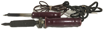
Vintage soldering irons for electronics work. Interestingly, when transistorized circuits first began appearing in televisions and radios, many service shops were not happy with them due to the smaller parts being more difficult to handle and the frequent lifting of metal traces lifting from PCBs when their standard equipment soldering irons designed to join copper rain guttering were used. Printed Radios - Big Changes on the Way
When radio was young and known as "wireless," we used to buy our various radio components, tubes, variable condensers, tuning coils, etc., and assemble them on a breadboard. We then proceeded to wire the components in exactly the same manner in which electrical instruments always have been wired. In the early days practically all radio components had some sort of binding posts to which connections were made. Soon when hundreds of thousands of people wanted radio receivers, the same components were still used, but the binding posts and screw connections no longer could pass muster. The reason was that such connections were not sufficiently good electrically and soon became loose due to temperature variations, vibration, etc. Then the set became inoperative. The binding posts now gave way to the soldered connection. This proved a step forward because such connections were made faster; dozens of connections were quickly made once the soldering iron was hot. This method is still in vogue today under mass production conditions of radio set manufacture. Later on when it became necessary to turn out thousands of radio receivers daily, radio manufacturers borrowed a few tricks from the automobile makers and began to assemble radio sets on an endless belt where special operators, standing along the production line, made a few soldered connections as the radio chassis moved by them. The solderers had to work fast, and at the same time the soldered connections had to be perfect, too. Thus we see the modern radio chassis moving on long belts, each operator doing his assigned part until the final, completely assembled and soldered chassis comes off the production line, which then goes to the testing benches. During the war, when speed in assembling and compactness of certain radio and radar sets became a paramount consideration, new ways and means had to be developed in order to turn out a rigidly perfect product in a minimum of time. Engineers pored over already existing patents to find ways and means to do away with wiring entirely. In their search they came across a number of patents dating back to the early 30's wherein some inventors had foreseen just such an eventuality and had patented solderless and wireless radio receivers. These inventors recalled that it was not necessary, for instance, to use a three-dimensional resistor because in the early days of radio when the audion first was invented by de Forest, a high-resistance grid leak, having a resistance of several hundred thousand ohms, was fashioned in a very simple manner. All that was necessary was to trace on a small card, such as a visiting card, a heavy pencil line and then make connections with two brass clips on each side of the pencil line. This pencil line was the resistor. Later on the pencil line gave way to an India ink line traced by means of a pen on paper. Connections were made with metal clips, or similar means.
Later on engineers began to think along parallel lines. The idea of printing the wiring and various other components no longer seemed far-fetched. It was found, for instance, that you could take a sheet of Bakelite, or other plastic, and electroplate such a sheet with a maze of connecting lines in order to fashion a "chassis" on which radio parts could be screwed down. The electro-plated lines had now become the connecting wires. Several other methods were developed in addition to electroplating. A number of prominent ink houses found that an intricate mass of wiring could be printed on an insulating sheet by means of a special high-conduction ink. These printed ink lines were the connecting wires. If certain of the lines were not sufficiently conductive to carry the necessary amount of current, the ink lines could be plated or sprayed with copper or other metal. Another process tried was that of depositing metallic silver on an insulating sheet. The silver can be deposited chemically or electrochemically; it can also be painted on ceramics.* Silver being our best conductor, a very good connection was thus fashioned, in fact, as good as a solid copper wire. By means of these various methods an entirely new art is now being developed. The radio chassis of the future will have all its wiring permanently printed in place. Then when the chassis comes to the assembling line the . radio receiver can be put together in a small fraction of the time it takes to do by the present methods. Inventors found that while it is easy to print or plate on an insulating sheet, more difficult is the problem of lines that must cross each other. Naturally, you cannot print or plate cross "wiring-lines" on the same surface, because this would cause short-circuits. Inventors got around this by placing the connection lines on both sides of the sheet. Thus there can be no short-circuit, yet all the "wiring" can be put in place. Now when two connection lines cross each other, they cross with a solid sheet of insulating material between them. After that problem was solved, radio engineers asked themselves why they should stop with the connection lines. So they began to evolve printed components. Just as the writer originally printed grid-leak resistors, so now engineers are beginning to print on the chassis certain resistors, using special inks for the process. It is conceivable that in due time most of our resistors on our radio chassis will be printed instead of being three-dimensional. Inductors also are simple to print. We already have printed or plated helices, which work just as well, if not better, than three-dimensional ones.
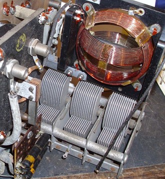
Restored inductive variometer seen on the TubeRadio.com website - an impressive piece of work! It seems quite possible that actual tuning will be done in the near future, where two spiral line inductances are printed on two separate thin insulating sheets. Then tuning can be accomplished by sliding one sheet over the other. A somewhat similar method was used many years ago in our old-time variometers. It is conceivable that cheap radios of the future will have some such variometer-tuning which will entirely do away with variable condensers. Built-in antennas can be easily fashioned in the above described manner simply by printing or plating the antenna spiral inductance. TThis brings us to the capacitors, or condensers, used in radio sets. Is it possible to use printed capacitors in the radio set of the future? We believe so, particularly with the smaller capacitors. The manner in which radio condensers are mass-produced today is probably as efficient and economical as can be done by the plating or printing method. Yet there may be exceptions here, too, particularly with those condensers which must take up a minimum of room. No matter how thin you roll aluminum or tin foil (as used in present-day condensers), it still takes up quite a bit of room, particularly where the capacity of the condenser is high. Perhaps it will be more economical and practical to print on the dielectric such as wax-paper, with a conducting link. Then after the condenser is rolled up in the usual fashion, it will be much thinner than the metal-foil type. (Incidentally, the Germans perfected a metal sprayed paper for condensers, during the war.) Printed condensers of this type probably will be used sooner or later in our pocket radio sets where even a 64th of an inch thickness of a component becomes a big factor. Such a condenser also will have its uses in many military radios, pocket transceivers, proximity-fuse radios, miniature radars, etc. The matter of connecting the various components to the printed components has taken much ingenuity to solve. When, for instance, your chassis with its printed connections, its printed inductances, and its printed resistors are ready for final assembly, it is still necessary to make further connections such as the radio tubes. The tube prongs must be connected in a positive manner to the printed or plated connections. This problem, however, has already been solved and new improvements are being made right along. Special brass ferules with flanges are used to make positive connections that need not necessarily be soldered. These brass ferules, or fingers, made of a hard springy brass, that is always under tension, are forced through certain prefabricated holes. When these brass fingers, or clips, are then machined into place they make a permanent and excellent contact with the plated or printed strips. Then when the radio tube is inserted in the usual manner there will be no loose connections. It has been found that printed resistors do not change appreciably over a long period of time. The expansion and contraction coefficient is very small and there is practically no deterioration. All of this can be further safe-guarded by placing a final insulating lamination on top of the printed or plated connections so that all dust is kept out. Now the chassis with all of its printed resistors, components, and connecting strips is hermetically sealed; no moisture or dust can get in between the two sheets. This can be further improved if the set is to work in the tropics. For instance, by sealing the edges off with some special compound the entire chassis is made moisture- or water-proof. Why is this new radio development so important at present? It is of a purely economic nature. Radios are selling today for more than 50% above their price before the war. And it is axiomatic that the more labor is expended on a radio receiver the more expensive it will be. In the United States, as everywhere else in the world today, it is not the cost of the materials that makes the price of the radio set. It is the high cost of labor which is many times that of the materials. Hence, it can be seen how important the new printed radio development is and how anxious the radio industry is today to convert to this type of radio as fast as possible. Not only will the printed radio receiver be much lower in price, but it is an ideal article for mass production under present-day conditions.** There is another even more important consideration, i.e., the servicing of radio sets. Today when a radio serviceman services a receiver and locates the trouble it becomes a matter of labor to put the set into operating condition again. Sometimes when it is difficult to locate the trouble it may take several hours to find it, for which time the serviceman must charge. There may be troubles such as intermittent contacts and other "bugs" which makes it most difficult to locate the trouble. Now let us consider the printed radio of the future and note how it will be serviced. Forward-looking engineers already have visualized a radio chassis with all the major components except the loudspeaker, tubes, etc. The entire chassis will be composed of a few insulating laminations less than a half-inch thick. This, then, is the future chassis of your radio. It can be snapped into position in a few seconds and snapped out again if desired. In the future when the serviceman finds burned out resistors, or some other trouble that is likely to mean several hours of work, he simply will snap out the laminated-sheet chassis, throw it aside and snap in a new chassis. Such a replacement chassis should not cost the serviceman more than $1.00, even for a 6-tube superheterodyne. In a matter of seconds the set will play again. When the chassis is put back into its cabinet, as far as the serviceman is concerned, the job is finished. The old chassis is simply discarded, as it will not pay anyone to spend much repair time on it; it could not be taken apart successfully anyway without special tools. As the new chassis costs very little, the customer practically gets a new set for very little money. Many books can and will be written on the subject of printed radios. While we have described the new technique only sketchily for the purpose of this article, the reader should understand that we still are at the beginning of this revolutionary radio idea. During the next few years many other improvements will be added to this new art. ** See also article "Why No 'Postwar' Radios?" by H. Gernsback, August, 1946 * See article "New Subminiature Printed Circuits," June, 1947 Radio-Craft.
Posted July 3, 2020 |
|

 By Hugo Gernsback