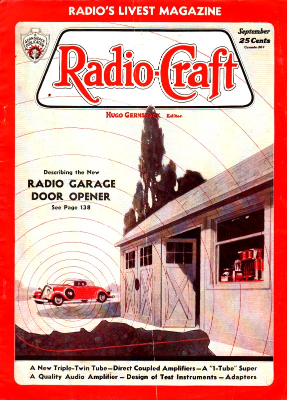
The New Radio Garage Door Opener
|
|
Only a couple decades prior to when this article on a newfangled wireless automatic garage door opener appeared in Radio-Craft magazine, there would have been no demand for such a device ... although maybe an automatic horse barn door opener would have been in demand if a battery was available on the coach. Amazingly, the system employed an early, albeit crude, form of both spread spectrum and digital communications in order to trigger the receiver for opening the door. The spread spectrum characteristic of the signal was the natural consequence of using a spark transmitter. A digital 'Morse' code encryption allowed multiple openers to be installed in close proximity. The opener did not have any type of safety sensor to prevent people or things from being crushed, but then it wasn't until sometime around the 1970s that the feature became standard, and probably the 1980s before it became mandatory. The New Radio Garage Door Opener
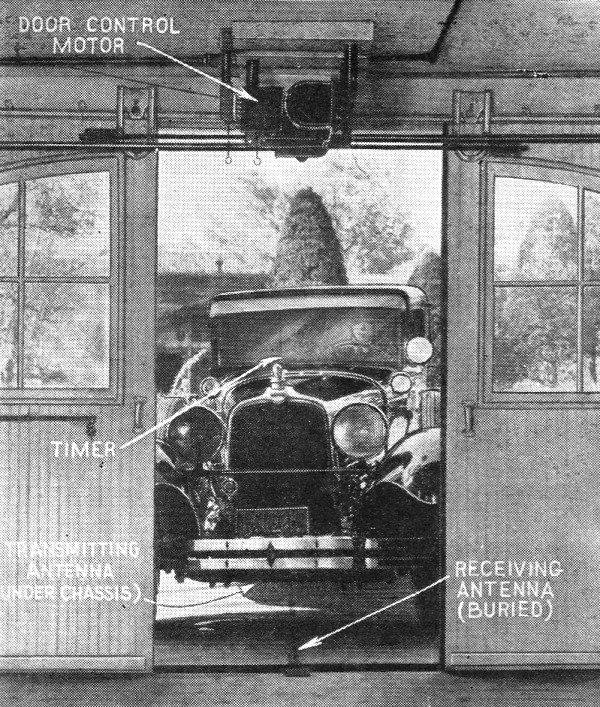
Fig. A - A view from the inside of a garage showing the location of the equipment.
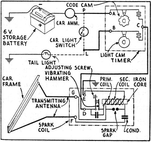
Fig. 1 - A diagram of the transmitter used in the radio-controlled door opener. Note that the car frame is used as the radiating system.
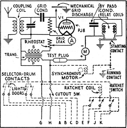
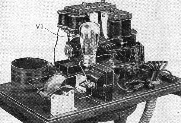
Fig. 2 - Diagram of the receiver pictured in Fig. C.
Fig. B - The illustration at the upper right shows the location of the timer while the larger photograph shows the location of the spark-coil transmitter.
Fig. C - A close-up of the receiver, usually mounted on one of the walls of the garage.
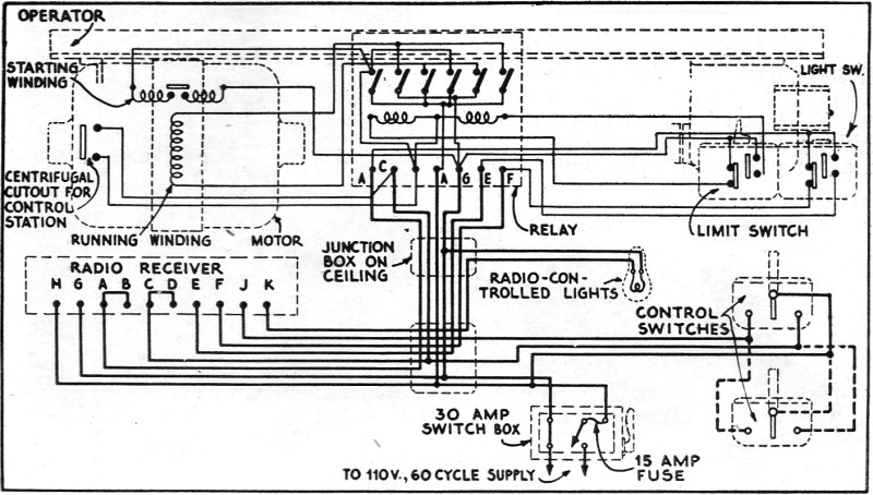
Fig. 3 - Complete schematic circuit of the motor and light-control circuits used in this system. The output of the receiver works "the works." R. D. Washburne A commercial system for the remote control of garage doors. etc. A 100-meter signal radiated by a transmitter located in, for example, an automobile is picked up by a receiver and, in turn, actuates a door-opening or closing motor. A "code" prevents tampering or accidental operation of the system. "Presto!" is the "open Sesame" which controls the door of the really modern garage. Press a button and, lo, the portals of your garage swing wide before you, lock open while you majestically continue your ride; and then, at a second press of the button, close and lock, whether you are leaving your garage or returning to it. We will now (with due apologies to the ads) disclose the "trick." A radio transmitter mounted in the automobile transmits a short-wave signal of "coded" or pre-determined dot-dash characteristics, when a knob on the instrument board is pressed. This signal is radiated by a one-wire antenna underneath the car chassis, and is picked up by a one-wire antenna buried in the driveway. The latter antenna is connected to a receiving set which "de-codes" the signal, and then operates motors which control the opening, closing and locking of the garage doors. Literally, the system is a "radio key." A display at A Century of Progress illustrates this procedure. An idea of the relative parts arrangement may be obtained by reference to the cover illustration and Fig. A. A schematic circuit of the radio transmitter located in the car is shown in Fig, 1. The receiver connections are shown in Fig. 2. The door motor, which operates only when a particular set of signals is received, connects to the receiver as shown in Fig. 3. As shown in Fig. 1, a simple spark coil arrangement is sufficient for the transmitter requirements of this installation. The transmission is rather broad, on a wavelength of 100 meters. However, the field of radiation is confined by the body of the car almost entirely to an area immediately underneath the car, thus preventing interference on nearby receiving sets, Such slight interference as may be introduced on extremely sensitive receivers, or those operating on short waves, is of little consequence as the units operate ordinarily at considerable intervals, and then only for about three seconds. The spark coil unit is contained in a water-tight case and is bolted to the underside of the car chassis. The transmitter timer, shown only in schematic form in Fig. 1, clamps to the instrument board, and consists of a rack-and-pinion arrangement incorporating a balance wheel, escapement wheel, hairspring, pallet lever, and a contact plate and contact springs. The rack-and-pinion mechanism is controlled by a plunger. The timer action is set at the factory with a combination which is different for every installation. It is put into operation by a thrust on the plunger which extends from the lower edge of the instrument board of the automobile. Since a similarly-coded action is installed at the receiver, it is not possible for static, or the radiations of a transmitter not equipped with the same code, to actuate the door motor. In reference to the diagram of the transmitter, the car wiring is shown in dotted lines; external wiring is shown in heavy lines; and, internal wiring is shown in light lines. Radio-Controlled Garage Lights! It is of considerable interest to note that the lights inside the garage may be automatically turned on and off by radio. This is accomplished by an added impulse in the code, which is transmitted only when the lights of the car are turned on (thus completing a section of the car lighting circuit which is wired to the radio control system). The antenna which connects to the transmitter is strung diagonally underneath the chassis. The receiving antenna, about 150 ft. long, is buried a few inches deep in the driveway. The receiver must be in continuous operation; consequently, the amplifier tube, V1, shown in Fig. 2, is specially designed for continuous operation over a minimum period of 2 1/2 years. For testing; this tube a D.C. milliammeter of 0 to 15 ma. range is connected into circuit at M; for the same purpose an A.C. ammeter of 0 to 2 A. range is connected at A. (This tube is of the type developed for use in automatic train control equipment.) The output of V1 actuates the de-coding mechanism, a set of relays and electromagnets operating a pawl-and-ratchet system that rotates worm gears and a number of discs which close contacts. One receiver can control, at will, either side of a 2-car garage. The stock receiver and door operating units are designed to operate on 110 V., 60 cycles, A.C. The components are protected by a metal shield-can; the assembly is mounted inside the garage, fairly close to the door-operating motor. A split-phase motor is used in the door-opening and closing system, the circuit of which is shown in Fig. 3. In this figure, heavy lines indicate external wiring. Any number of the manual control switches may be placed in con-venient locations. Although our major interest lies in the radio components, the action of the door control also is described. Power is transferred from the motor unit, when starting contact is made, to a latch magnet, by means of an arma-ture and spring-operated lever, releas-ing a brake and closing the main motor switch at the lever end. As soon as the electric motor reaches normal speed, in about one-half second, a centrifugal clutch engages and passes the motion on to a planetary differential which. forms the main part of the release mechanism. A pawl holds the ring gear fixed until the load exceeds a set amount, and then trips. This per-mits the ring gear to run free and the motor, which continues to run, is dis-connected from the driving pinion. The driving pinion causes the door to open or close. At the end of the door travel a cam shaft is automatically operated. It opens the main motor switch and ap-plies a brake which stops the door. At the same time the release mechanism is locked by a locking lever so that any attempt to force the door will not trip the release mechanism. Also, the motor control switch is shifted and the motor prepared to operate in the reverse di-rection on the next signal; an additional switch for controlling the lights also is shifted. Radio control of the garage door permits the motorist to enter or leave his car under shelter, a boon when it's "raining pitchforks," or in blizzard weather. Incidentally, the same princi-ples may be applied to the operation of doors within the home. The radio light control feature of this installation has several points of particular interest to the car owner. As the car is driven up the driveway and the door-control plunger is operated, the garage, driveway and yard are suddenly flooded with light, provided the headlights of the car are turned on-as for night driving. A conveniently located switch inside the house makes it easy to extinguish the garage and yard lights in case it is de-sired to leave them turned on until the owner is inside his home. This provi-sion minimizes the possibility of a ma-rauder lurking about, since all local areas become flooded with light. Thus, for a few hundred dollars the provi-dent person may possess a useful "magic wand." Installations throughout the country have proved that this "unseen servant" is an absolutely practical mechanism -another effective member of the radio "robot" family. Whether the Service Man will be able to obtain this equip-ment for private installation cannot be definitely stated at the present time. To date, all "radio door" installations have been made only by a corps of techni-cians trained by the manufacturer of the system.
Posted January 26, 2021 |
|