Limiting / Limiter Circuits
|
|
Solid state equivalent of vacuum tube diode Often when posting this kind of circuit design and/or analysis article from a vintage electronics magazine like Radio-Craft I point out that except for biasing voltage and resistor values, most can conceptually be applied to solid state circuits by substituting semiconductor junction diodes for tube diodes and field effect transistors for tube triodes, tetrodes, and pentodes. In some cases solid state diodes can be directly substituted if the voltage, current, and power handling is sufficient. Many examples of using diodes as voltage limiting devices for the purpose of signal rectification, for leveling, and for protection against an overvoltage condition. Signal detection is another common use for diodes, but that is not covered here. As a visual aid, I created the graphic above to show how you can replace the vacuum tube with a semiconductor diode. Limiting Circuits Are Important in Radar, FM and All Pulsing Circuits
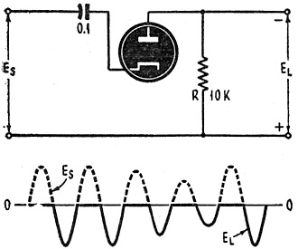
Fig. 1 - Positive limiting with series diode.
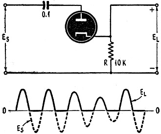
Fig. 2 - Similar to above, negative limiting.
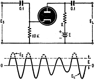
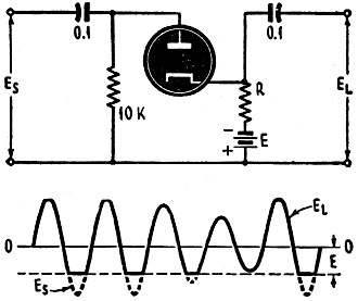
Fig. 3 - Series positive limiting ground.
Fig. 4 - Series negative limiting below ground.
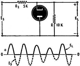
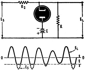
Fig. 5 - Positive limiter with diode.
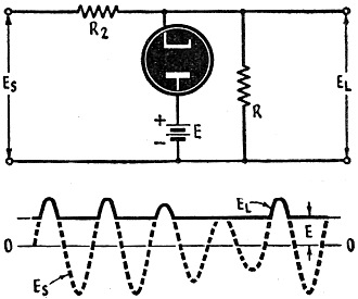
Fig. 6 - Negative limiting version of Fig. 5. By Jordan McQuay Amplitude of waves is of great importance in radar, television and electronics circuits. Control of wave amplitude is the function of limiters, sometimes known as clippers. Limiter removes one extremity or the other, or both extremities, of any form of input wave. In some applications the signal level may be reduced by a limiter, so the output never exceeds a certain datum. Or, only peaks above a certain reference voltage may be allowed to pass the limiter stage. Limiting action can be accomplished by varistor's, or similar devices whose resistance decreases with rising voltage. Selenium and copper-oxide rectifiers also provide some limiting effects. But such devices are difficult to control, lack precise definition, and are none too dependable for exacting work in electronics. Most effective means of precision limiting is by vacuum tubes. Diodes, triodes, and even pentodes are used for such amplitude control - connected in a variety of circuits, depending upon the type of control action and discrimination required. For instance, a limiter may function as a protective device: limiting all amplitudes to 50 volts peak - since higher voltages might damage some later stage. Or, a limiter may be required to pass only those parts of an input pulse that exceed 30 volts - thus creating impulses above a certain reference level. A limiter can convert an input sine wave into a square or rectangular wave. A peaked wave can be converted into a steep-front pulse by removing positive or negative extremities. Thus, a limiter may be used as a wave-shaping circuit, in addition to its amplitude discrimination duties. Limiting circuits are classified according to five types: (1) Series diode limiters, (2) Parallel diode limiters, (3) Double diode limiters, (4) Triodes, tetrodes, and pentodes with grid limiting, and (5) Overdriven amplifiers. Inclusion of overdriven amplifiers in the class of limiting circuits is entirely accurate, even though such devices are occasionally referred to as square-wave generators. The Diode Principle Conduction takes place in a diode vacuum tube only when the plate is. positive with respect to the cathode (or the cathode is negative with respect to the plate). Under such conditions, electrons pass from the cathode only in the direction of the plate. This unilateral characteristic of the ordinary diode makes it ideal for limiting purposes. If the cathode is grounded, the plate must be positive with respect to ground for conduction to take place. If a fixed positive voltage is applied to the cathode, the diode will not pass current until the plate has risen above an equal positive voltage. In much the same manner, if the cathode is biased below ground potential, the diode will conduct only when the plate is above the negative value of the cathode voltage. Current begins to flow in the diode circuit when the plate is first made positive with respect to the cathode. As the plate becomes more positive, the flow of current increases rapidly and the internal resistance of the diode diminishes to a few hundred ohms. Use of the diode as a limiter permits control of the threshold of action over wide limits of voltage. The output wave will be a direct function of the input signal for any type of diode limiter, and, neglecting minor circuit losses, a unity transfer of energy can be expected. The same wave-train of varying amplitude is used to illustrate the function of all of the following limiter circuits. But the limiter action is independent of the form or shape of the input wave. Simplest diode arrangement is a series limiter circuit in which the tube functions much as a rectifier or polarity switch. When the input signal Es is applied to the series diode circuit (Fig. 1), the tube cannot conduct during positive alternations, because the cathode is positive with respect to the plate. In addition, the resistor R is large enough to prevent any small current flow. Therefore, during positive portions of the input signal there is no output voltage. During negative alternations, however, the diode conducts normally. Polarity of the output voltage EL developed across the resistor R is the same as the applied voltage of the signal. Series Diode Limiters This circuit (Fig. 1) provides what is known as positive limiting, since a positive portion - in this case, all of it - is limited or removed from the input. By merely reversing the diode connections, the circuit (Fig. 2) can be used to limit negative portions of the signal voltage. In this arrangement, the tube conducts only during positive alternations. There is no output voltage EL during negative cycles of the signal. These two simple series circuits (Figs. 1 and 2) limit the input wave to the base line or zero axis, in true rectifying manner. Often in radar and electronics work it is necessary to provide positive or negative limiting at some fixed value above or below ground. When a fixed positive voltage is applied to the plate, a diode conducts at all times except when the positive swing of the input signal to the cathode exceeds this voltage. Such a series diode limiter (Fig. 3) provides positive limiting above ground. And the positive voltage level (above ground) depends upon the amount of fixed positive voltage E. When the input signal Es is applied to this circuit, all voltages having a positive value greater than the bias voltage E will stop the diode from conducting. All positive peaks will be "clipped" or limited. Since the amount of bias determines the amount of positive-peak limiting, a negative bias voltage E would result in extreme limiting of the positive peaks. This level of limiting would be below ground. By reversing the diode and bias connections, as shown in figure 4, the negative peaks of the input signal can be limited below ground. All portions of the input signal Es having a negative value greater; than the bias voltage E will stop conductance of the diode. Since the amount of limiting is determined by the bias voltage E, a positive bias voltage would result in extreme limiting of the negative peaks, or a limiting action above ground. Parallel Diode Limiters If a limiting diode is connected in parallel with the circuit load, during periods of tube conductance unwanted energy will be short-circuited and effectively dissipated without appearing in the output. Such an arrangement (Fig. 5) provides positive limiting action. Since the cathode is at ground potential, all input voltages above ground cause the diode to conduct. When the input signal Es is applied, positive alternations thus cause a current flow through the tube and through the series resistor R2. As this resistor is large compared to the internal resistance of the tube, positive portions of the input wave are dissipated and do not appear across the load resistor R. Negative alternations of the input Es are unaffected by the parallel diode, and are reproduced in the output without distortion. By merely reversing the connections of the diode, negative limiting can be provided (Fig. 6).
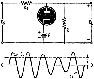
Fig. 7 - Positive limiting above ground with a parallel diode circuit.
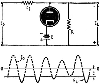
Fig. 8 - Positive limiting below ground with a parallel diode circuit.
Fig. 9 - Below-ground parallel-diode limiter.
Fig. 10 - Above-ground parallel-diode limiter.
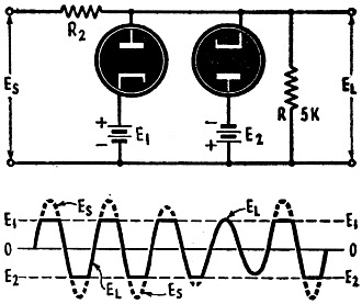
Fig. 11 - Both positive and negative limiting can be accomplished with a double-diode tube.
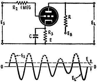
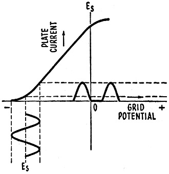
Fig. 12 - Triode positive circuit.
Fig. 13 (a ) - Plate cut-off negative limiting.
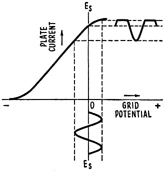
Fig. 13 (b) - Waveform from overdriven amplifier.
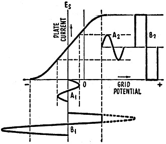
Fig. 14 - Waveform from overdriven amplifier. Action of this circuit is similar to that just described. But negative portions of the input signal are dissipated in the series resistor R2. And positive portions are unaffected by the parallel diode. The two circuits (Figs. 5 and 6) limit the input wave to the zero axis, or ground potential. Since it is often desirable to limit the signal voltage to some established positive or negative reference level, a fixed voltage can be introduced to one or the other of the diode electrodes for this purpose. In the parallel limiter circuit (Fig. 7), the cathode of the tube is more positive than the plate by the amount of the fixed voltage E. Whenever positive cycles of the input exceed the voltage E, the tube conducts and the voltage is dissipated in the resistor R2. However, when the input does not exceed the fixed bias voltage, the diode will not conduct. And the output will be an exact replica of the input signal. This circuit provides positive limiting at a given volt-age above ground. Positive limiting below ground can be achieved by merely reversing the polarity of the bias voltage E. When the input Es is then applied to the parallel circuit (Fig. 8), the diode conducts at all times except when negative alternations exceed the fixed voltage E. Thus most of the input signal, is dissipated in the series resistor R2. Output consists of a series of negative-going impulses. Negative limiting below ground is accomplished-by the circuit shown in Fig. 9. The bias voltage E prevents the diode from conducting during all of the positive and most of the negative alternations. But when the negative swing of the input exceeds the voltage E, the tube conducts and this energy is dissipated in resistor R2. Reversal of the voltage E permits the same circuit to provide negative limiting above ground (Fig. 10). In this case, the diode conducts at all times except when the positive alternations exceed in amplitude the voltage E. The output of this parallel diode limiter is a series of positive-going impulses. Double Diode Limiters Since one parallel diode can be used to limit either positive or negative extremities of an input signal, it is apparent that two diodes can be used to limit both amplitudes in the same circuit. Such an arrangement is shown in Fig. 11, where positive and negative limiting is performed by two diodes, or a double diode. Maximum amplitudes of the output EL depends upon the values of the fixed bias voltage for each diode. Output is developed across the load resistor R. An examination of the output wave reveals that this circuit (Fig. 11) is a simple means of producing a square or rectangular wave output from a sine wave input. The circuit is occasionally used in electronics for this sole purpose. Two series diode limiters could be connected together to perform a similar, double-limiting function, but such an arrangement requires much more critical adjustment and is seldom used. Grid Limiting Any triode, tetrode, or pentode can be operated as a limiter by utilizing the cathode-grid circuit in the manner of a simple parallel diode. The circuit (Fig. 12) requires the use of a large series grid resistor R2 which acts very much as a grid leak. During negative cycles of the input Es no grid current flows in the circuit. There is no voltage drop across the resistor R2 and the entire input signal appears between the grid and cathode of the tube When grid current flows, however, during a portion of the positive alternations of the input, there is a voltage drop across the large grid resistor - leaving only a small part of the positive input voltage to be applied to the tube. The point at which grid current begins to flow is determined by the bias "E," developed between grid and cathode by the flow of plate current through the cathode resistor R3. This effective bias voltage "E" establishes the limiter level. Grid of the tube is normally at ground potential, and thus is negative with respect to the cathode. Positive alternations drive the grid positive by an amount equal to the voltage value "E," before the bias effect of the cathode resister is removed. Any further rise in the positive input signal then results in attenuation by the grid circuit. Negative portions of the input are passed by this circuit without change or limiting. Cut-Off and Saturation Ordinary triodes, tetrodes, and pentodes can also be operated under conditions resulting in two other types of limiting action. Considering the Ip-Eg characteristic curve for any triode, a central portion of the curve will usually be almost linear-permitting distortion-free amplification of input signals. However, if the tube is operated at or near the end (non-linear) regions of the curve, the output wave will be distorted. For example, the operating point on the characteristic curve could be chosen at such a value that the negative portions of the input signal would swing the tube beyond cut-off. (See Fig. 13 [a].) The negative alternation would then have some part of its extremity removed, but the positive cycle would he unaffected. This is known as cut-off limiting in an amplifier. If the operating point is chosen near the point of saturation on the characteristic curve (Fig. 13 [b]), the positive portion of the wave would be distorted and limited, while the negative part of each cycle would not be affected. This is known as saturation limiting in an amplifier. The chief value of these two new forms of limiting is that they may be combined in a single amplifier to provide both positive and negative limiting with a single tube. All that is required is an input signal of such great amplitude that (1) it drives the amplifier tube far into the cut-off region on negative alternations, and (2) it drives the tube far beyond the saturation region on positive alternations (Fig. 14). Such a device is known as an over-driven amplifier. The combination of cut-off and saturation limiting is used to produce a square or rectangular wave from a high-amplitude input sine wave. Referring to Fig. 14, assume that the normal input A1 of 50 volts results in a linear output A2. The triode, however, is purposely operated with an excessive input B1 of 400 volts, or higher. Then, as the grid swings positive a condition of saturation will be reached quickly - and the output B2 will have risen to its greatest possible value. As the grid attempts to go more positive due to the driving influence of the input signal, more and more grid current will be drawn by the amplifier tube. The high impedance driving source will be incapable of effecting a further increase in the grid voltage. Thus, the output wave will remain at constant amplitude, until the signal input wave has proceeded in its cycle and returns to the linear portion of the characteristic curve. Once this region of linearity is reached, the output wave will fall proportionately with a decrease in grid voltage until it reaches the cut-off point. From that point any further decrease in grid voltage has no effect on the output wave, since it cannot be reduced below zero. Therefore, the output will remain at zero until the signal wave continues in its cycle and enters the region where the tube will pass plate current again, when the entire process is repeated. Thus, two characteristic limitations of an amplifier can be utilized to pro-duce a steep-sided square or rectangular output wave.
Posted June 1, 2021 |
|