India's New Network of Radio Broadcasting
|
|
When this story was published in 1938 in Radio−Craft magazine, India was a country of roughly 2 million square miles, while the 48 United States had about 3.1 million square miles. Radio station growth in the U.S. already had a three-decade head start in establishing a nationwide network of broadcast and receiving stations. Manufacturing of the required equipment was well established within our borders. India, by contrast, relied heavily on outside sources for equipment and the training of operators and servicemen. The U.S. never has had and still does not have an official "state radio" as was All−India Radio. A nice feature of the system was inclusion of a time-keeping signal that would allow anyone within the reception of a clear signal to synchronize clocks. The included map shows where the first four 10 kW main shortwave transmitters were installed in key population areas. The terms "direct−ray" and "indirect-ray" were used at the time to describe non−skip and atmospheric skip, respectively, propagation. India's New Network of Radio Broadcasting
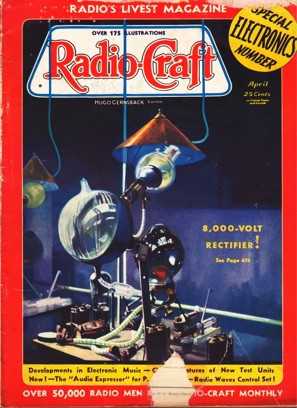
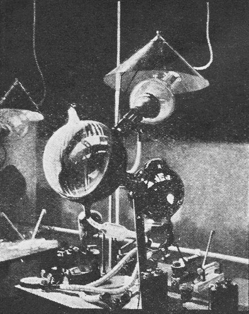
Fig. A - Reproduction of the cover painting showing the 8,000-V. Philips rectifier tube to be used in the new All-India Radio Broadcasting network. A new radio system, with broadcast band and short-wave transmitters and time clock operated, pre-tuned receivers in key villages, furthers India's plan for eventual complete coverage. An unusual feature of this new All-India Radio system is that the pre-tuned receivers are dial-less and padlocked; and that the 8,000-volt power-supply tubes use mica "lampshades" to reduce possibility of "backfire." The technical problem that now confronts the Broadcasting Department of the Government of India, All-India Radio, is that of providing a service over an area of nearly 2,000,000 square miles with the limited funds available, official announcements state. In the development of broadcasting in India it has been accepted by All-India Radio as a fundamental precept that a satisfactory broadcasting system must provide a measure of service to the whole country. This immediately determines the principle of operating transmitting stations on the short wave-lengths. At the same time, it is admitted that this is not a final solution. Simultaneously with the provision of a short-wave or "second-grade" service to the whole area, a medium-wave or "first-grade" service is necessary for the large towns. The basic principle of broadcasting development in India, therefore, is to provide a short-wave service to the whole country and to support this by a continual expansion of the area served by medium-wave stations as funds become available. 10 Transmitters Ordered
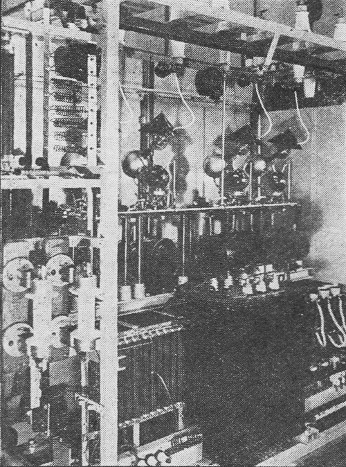
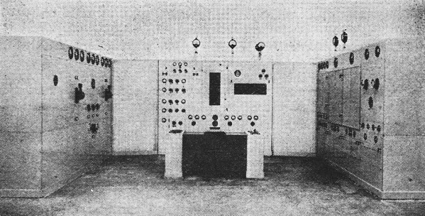
Fig. B - View of some of the power supply equipment for the transmitters. At the right is the bank of four 8,000 V. Philips rectifier tubes. To this end 10 transmitters have been ordered. Four short-wave "key" stations will be established at Delhi, Bombay, Calcutta, and Madras, and will be of 10-kw. (aerial) power. A second short-wave transmitter of 5-kw. power is also to be provided at Delhi for special purposes. The development program does not envisage any future increase in the number of short-wave stations. These short-wave stations will provide a "second-grade" service to the whole of India. At the same time, 5 medium-wave stations have been ordered, and will be situated at Lahore, Lucknow, Trichinopoly, Dacca, and Madras, the first 4 stations having a power of 5 kw. The Madras medium-wave station will have a power of 250 watts, and will service the city only, as Madras will also be provided with a 10-kw. short-wave transmitter. With these stations, and the existing medium-wave stations at Delhi, Bombay, Calcutta, and Peshawar, All-India Radio will have in operation 5 short-wave stations and 9 medium-wave stations. Two of the new stations are expected to be in operation by the end of the year: the 10-kw. short-wave station at Delhi and the 5-kw. medium-wave station at Lahore. Choice of Short Wavelengths It is expected that the Indian short-wave stations will normally operate in the daytime on the 30-meter and 49-meter bands and at night principally on the new 60-meter and 90-meter bands for broadcasting which will be proposed at the forthcoming Cairo Conference. It is considered that there should be no interference between the Indian short-wave stations operating an internal service and the European and the other short-wave stations operating an international service, as the Indian day wavelengths are the European night wavelengths, and the Indian night wavelengths are not used by the broadcasting stations operating an international service.
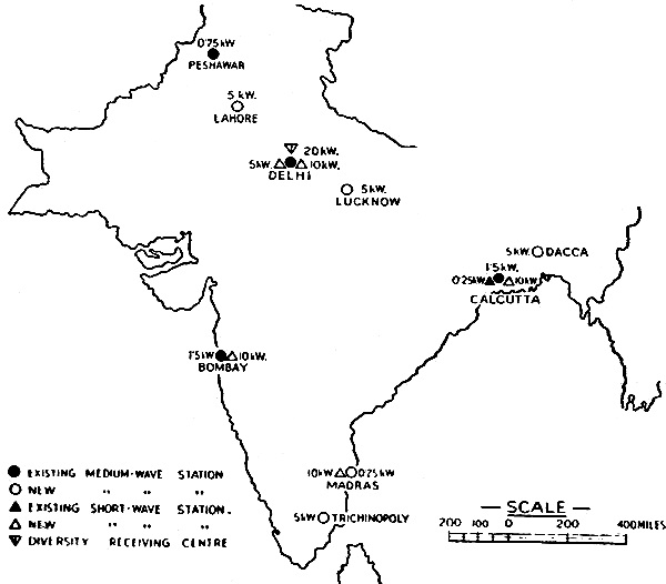
Fig. C - The map of India showing the locations of both the existing and the contemplated short-wave and medium-wave broadcasting stations. Only strategic spots, from the good-reception angle, were chosen.
Fig. D - Impressive view of the short-wave transmitters to be used in the new All-India Radio broadcasting system. Other transmitters will operate in the medium-wave band, thus providing day and night broadcasting. Direct and Indirect "Ray" Service The distinction which has previously been drawn between the use of medium wavelengths and short wavelengths for broadcasting in India is based on the principle that the technically "perfect" broadcasting service can be given only by use of the "direct ray". The range of the direct ray on the medium-wavelengths is, however, small, especially in India, where severe atmospherics are present for large periods of the year. In actual fact the area which will be covered by a first-grade direct-ray service when all the medium-wave stations envisaged in the development program are in operation will be approximately 2% of the total area of India. The fundamental importance of the short-wave, indirect-ray service is therefore very evident. It may be asked why indirect-ray transmission is not satisfactory on the medium waves. In Europe good long-distance, indirect-ray reception is sometimes obtained, but this is possible only because of the relative absence of atmospheric disturbances. These depend upon wavelength and their strength is, in general. proportional to wavelength: the shorter the wavelength, the less the atmospheric disturbance. It is desirable, therefore, to choose as short a wavelength as possible to avoid atmospheric disturbances, and this is limited only by the intervention of the phenomenon of "skip distance". Sets for Village are padlocked! An unusual requirement in receiving-sets for India which deserves special mention is provided for by the special receivers that have been developed by the Research Department of All-India Radio for community reception in Indian villages. These receivers are mounted in metal cases and padlocked. No controls appear outside service. the box. The receiver is left tuned to the local station. A clockwork time-switch mounted in the box turns the set on and off at the correct time for the "Village Hour". The only attention required is a visit once every 3 weeks, when the car-type storage battery which operates the receiver is changed and the clock rewound. Village-receiver schemes are now in operation in the service areas of each : of the existing medium-wave stations, and a number of new projects will come into existence as soon as the new stations are in operation. (The foregoing material was supplied by Radio Press Service. Paris, France) The 8,000-V. Rectifiers
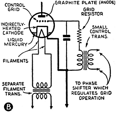
Fig. 1(B) - fundamental circuit of the Philips' 8,000-volt rectifier.
Fig. 1 - At (A) pictorial view of Philips' 8,000-volt rectifier. The new rectifier, which constitutes such a major contribution to the efficiency and effectiveness of the All-India Radio system, is the cover subject for this month's issue of Radio-Craft. This tube has a far lower internal resistance (and therefore, higher efficiency) than the vacuum rectifiers customarily employed. This feature also makes its cooling less of a problem. Figure 1A is a view of the tube pictured in Fig. A and on the cover and shows the essential elements. A schematic representation of the tube, and the means by which the rectifier can be controlled and regulated without making or breaking any mechanical contacts in the high tension circuit, are shown in Fig. 1B. One weakness of the tube was its liability to "backfire" under certain conditions, when the glow-discharge arcs over. This is remedied by placing the anode and cathode in separate chambers, with a third chamber between them. The mica "lampshade" above the tube keeps the upper chamber warm and prevents the condensation or mercury vapor at the anode which, incidentally, is made of graphite, a material which has low thermal emission.
Posted November 17, 2023 |
|