How the Audion Was Invented
|
|||||
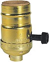
A few days ago I mentioned that a popular early form of radio detector circuit involved the used of a flame - yes, the flame of a fire, not a romantic significant other. The subject arose in a couple articles in the January 1947 issue of Radio-Craft magazine that celebrated the 40th anniversary of Lee de Forest's Audion vacuum tube invention. This particular piece was authored by de Forest himself, who was a personal friend of Radio-Craft editor Hugo Gernsback. It is a very interesting autobiographical account of the early days of experimentation and the evolution of what eventually became the world's first mass producible signal amplifying device. You will also read that de Forest created the designation of the "B" battery for a reason he makes obvious. Also, although you have probably seen pictures of the old household type gas light fixture, a look at the included photo of one shows from where the modern incandescent electric lamp bulb socket gets it shape - including the switch twist knob as found on 3-way sockets (see image below). How the Audion Was Invented
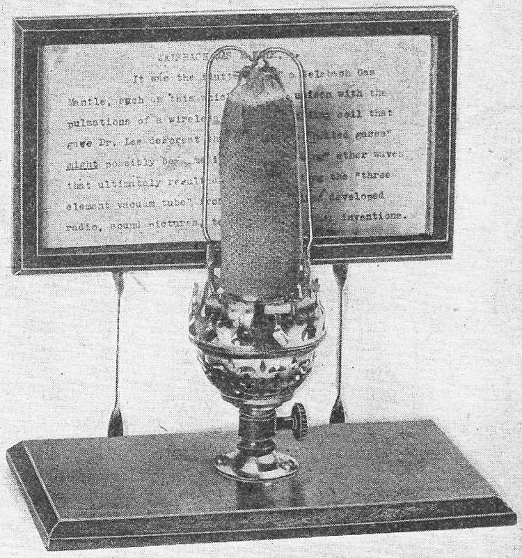
In the summer of 1900, I was working under the light of a Welsbach gas burner in my hall bedroom in Chicago, experimenting with my so-called "Sponder," an anti-coherer for the reception of electrical waves for use in wireless telegraphy. One night I noticed that whenever the little spark from my transmitter coil was put in operation the light from the Welsbach burner dimmed. When my transmitter key was lifted, (the normal light of the burner was restored. Thus I was able to translate into light variations the signals from my key. I was amazed and highly elated by this unexpected phenomenon, and for several weeks played with it, believing that I had accidentally discovered that incandescent gases were affected by Hertzian waves, and that here I had discovered an absolutely new principle which might be of the utmost value as a detector for wireless telegraphy. This illusion persisted until my assistant and I put the spark coil in a closet and closed the wooden door; thereupon the fluctuations of the gas burner were no longer observed. This proved conclusively that the effect observed was not due to the electrical waves from the spark, but to the sound waves therefrom. I had merely hit upon a new type of sensitive flame. I was intensely disappointed by this outcome, but I was positive that there must be, nevertheless, some change in the conductivity of incandescent gases resulting from the passage there through of high-frequency electrical waves, and I determined to investigate further and prove that my original conception had a basis in the physics of gases. Early Flame Detectors It was not until 1903, when I was working in a small laboratory at 11 Thames Street, in lower Manhattan, that I had leisure and opportunity to resume my work in this direction. There I used a Bunsen burner, locating within the flame two platinum electrodes, one of which was connected through the telephone receiver to a dry battery, and thence to the other platinum electrode. I enriched the flame with sodium, or common salt. I then found that when the electrodes were properly located in the gas flame the signals from my spark transmitter were distinctly audible in the telephone receiver. I made countless experiments with this phenomenon; and to prove definitely that the effect was not acoustic but electrical, I connected one of the flame electrodes to my antenna, the other to the ground, and actually obtained wireless signals from ships in New York harbor. Realizing that a gas-flame detector would be wholly unsuited for practical wireless work, I thought of other means for heating the gases. I tried a small electric arc - which was altogether too noisy to be of any use. After several futile attempts to build such a device myself, I persuaded Mr. McCandless, a manufacturer of miniature incandescent lamps, to build for me a tube containing a platinum plate and carbon filament. The plate was connected to the positive side of the dry battery; the negative terminal to the filament. In series was a telephone receiver. This device was not the Fleming valve. It has always been quite impossible for me to understand the confused idea, in the minds of some otherwise keen thinkers, that the audion differed from the Fleming valve merely by the insertion of a third electrode therein. Without the use of the B-battery the valve would be nothing but a rectifier with one too many electrodes. The employment of the local battery in the plate circuit is just as necessary an element to the success of the device as is the grid-itself. At the time I was working on the two-element audion with B-battery, I had never heard of the Fleming valve. My approach to this perfected device was by an entirely different series of events, and began with the gas-flame detector. Vacuum-Tube Detectors This device was a genuine relay, in which the local energy of the plate battery supplying the current through the remaining gas in the tube was controlled by pulsations of the incoming high-frequency waves, which were picked up on an antenna connected to the plate electrode, the filament being connected to the ground. This was the same arrangement I had previously used with the gas flame detector. At that time I had requested McCandless not to exhaust the tube to any high degree of vacuum, because I then thought that the presence of gas was an essential element. This diode detector, as stated above, was intrinsically very much more than a simple rectifier of high-frequency current. The addition of the plate battery made a very great difference in the intensity of the signals received, for I was employing the high-frequency energy, not to actuate my telephone diaphragm, as Fleming had done, but to control very much larger quantities of. energy from the local battery. I argued that the above arrangement was imperfect because it permitted part of the high-frequency energy to pass to earth through the telephone and B-battery circuit, instead of concentrating it upon the ions between the plate and filament. To avoid this difficulty and still improve the sensitivity of the detector, I wrapped a piece of tin foil around the outside of the cylindrical-shaped gas envelope, and . connected this third electrode to the antenna or to one terminal of the high-frequency device. I then realized that the efficiency could be still further enhanced if this third electrode were introduced with-in the envelope. I induced McCandless to construct another "audion," as I then called it. This last device contained two plates with a filament located between them, and, as before, a considerable amount of gas in the envelope. This detector showed further distinct improvement over its predecessors. The Grid Audion
Welsbach gas mantle, starting point of the series of experiments which led to the audion. It occurred to me that the third, or control, electrode should be located more efficiently, between plate and the filament. Obviously, this third electrode so located should not be a solid plate. Consequently I supplied McCandless with a small plate of platinum, perforated by a great number of small holes. This arrangement performed much better than anything preceding it, but in order to simplify and cheapen the construction I decided that the interposed third electrode would be better in the form of a grid, a simple piece of wire bent back and forth, located as close to the filament as possible.
3-Way Incandescent Lamp Socket At this time I was using a 6-volt filament energized from a dry or storage battery, which I called the A-battery; the plate battery I called the B-battery - terminology which has persisted to this day. As the various experiments and improvements outlined took place during the period 1903 to 1906 and later, I applied for successive patents. At that time the Patent Office was not glutted as it is today, and my applications were related to an entirely new art, so that the Office issued my patents within only a few weeks or few months after filing. Early in 1907 I conceived the idea that this remarkable wireless telegraph detector, the three-element, or grid, audion - which had already covered itself with glory in the minds of the hams and wireless telegraph operators - might also be useful as an amplifier of audio-frequency or telephonic currents. I had made some experiments in this direction, and I took out a patent containing very broad claims on the device as an amplifier of currents without limitation of the frequency thereof. This patent, No. 841,387, granted January 15, 1907, has since been acclaimed as one of the most valuable patents ever issued by the United States Patent Office. The same, of course can be truthfully said about the patent on the grid electrode, No. 879,532, filed January 29, 1907. In the summer of 1906 I presented a paper before the American Institute of Electrical Engineers describing the audion, but only as a diode using the B-battery. I had not then applied for a patent on the grid, or control-electrode, type, and therefore I made only veiled reference in this paper to it. The grid patent was filed on January 29, 1907. Early Types of Audions The first audions were of cylindrical form; later, in 1907 or 1908, McCandless suggested that it would be easier for him to construct the device in the spherical form. In the first audion the grid and plate electrodes were both brought out near the base; but in 1907 the plate and grid electrodes were brought out through the top of the tube. To distinguish readily between the two, I used a red sleeving over the lead to the plate, and a green sleeving over the grid wire - "green for grid," to be easily remembered by the operator. In my first experiments on the audion as an amplifier for telephonic currents I added a third, or C-battery as I called it, in series with the control electrode. Although, unfortunately, I did not specify the polarity of this C-battery, the circuit diagram of the amplifier patent shows it with its negative terminal connected to the control electrode. This was the way I always employed it; but due to this unfortunate omission from my specification, Fritz Lowenstein was able, a few years later, to obtain a very valuable patent covering the negative bias of the grid. He was, however, by no means the first to apply this negative bias to the control electrode. Later Audion Improvements
Evolution of the audion. Even the earliest flame detectors incorporated the B battery, as shown in the left-hand figure (Patent No. 867,878). The circuit at center (Patent No. 836,070) is essentially the same, with a heated filament in a low-vacuum tube taking the place of the Bunsen burner flame. Thus the B battery was also a feature of the earliest two-element audions. In the circuit at right (Patent No. 841,387) we see the separation of r.f. and local circuits, as well as the C battery (credit for the invention of which was lost to de Forest because polarity markings were omitted from the patent drawing). Obviously the whole series of heat detectors were thermionic relays, not simple rectifiers. From 1906 to 1910 I made countless improvements or changes in the form of the audion, such as the substitution of tantalum and then tungsten for the carbon filament; the use of nickel for plate and grid instead of platinum; the double filament so arranged that if one burned out the second one could be readily connected, thus doubling the life of the detector. As early as 1907 McCandless began to pump my tubes to the same vacuum he employed in his miniature incandescent lamps. Naturally some of the tubes contained more gas than did others, and we found that a very small amount of gas made the device a more sensitive detector than those of higher vacuum. When used as a detector of wireless signals, the lack-of-linearity characteristic was of course of no importance - maximum sensitivity was what we all were after. But so long as only an "incandescent lamp vacuum" was employed, it was impossible to use more than 22 or 30 volts in the B-battery without producing the "blue arc" which at once rendered the device extremely insensitive. My patents show types of audions employing two, three, or more grids, as well as the "double audion" having one plate and grid on either side of the double filament. The latter arrangement developed into a beautiful oscillator, the first push-pull type in electronic history. It was not until the summer of 1912 that I actually succeeded in developing the audion and its accompanying circuits into a genuine amplifier of telephonic currents. Seeking to make this amplifier more efficient and able to handle larger power, I besought McCandless to exhaust the tubes to the highest possible degree, to permit the use of more plate voltage. But the best that he could do still restricted this voltage to about 45. Thereupon I took some of his tubes to a manufacturer of X-ray tubes in San Francisco, who re-exhausted these to the best of his ability, using mercury vapor diffusion pumps. (McCandless had used only mechanical pumps.) With these re-exhausted tubes I was able to use as high as a 220-volt plate battery, without causing the "blue arc." Three of these high-vacuum audions connected in cascade gave amazing audio-amplifier effects, so that using, as my input source a telegraphone wire on which music or speech had been recorded, and as my output device a loudspeaker of the 1912 vintage, I was able to hear the reproduction of voice and music over a distance of 100 feet or more in the open air. Thus it is evident that the approach to the radio, or amplifier, tube possessing an extremely high vacuum was merely a gradual, and perfectly obvious, result of the growing requirement for more power from the amplifier or the oscillator. More power demanded higher voltages, and it was obvious that higher voltages would necessitate higher degrees of vacuum. I never considered for a moment that there was any invention involved in the gradual evolution of the audion from a gaseous, or low-vacuum, to a high-vacuum device. At this point in the development of the audion amplifier I was requested by my good friend John Stone to bring my demonstration apparatus from Palo Alto, California, to show to the engineers of the telephone company in the Western Electric laboratory in New York. From that point on, the further development and refinement of the audion amplifier to its present degree of ultra-perfection is well-known electronic history, and requires no resume here. Regeneration and Oscillation During those epoch-marking experiments in Palo Alto, in the summer of 1912, I accidentally hit upon the feed-back circuit, which made of the audion amplifier an oscillator of currents of any frequency. Thereafter began the intensive development of the "oscillion," as I then called it, in larger and larger sizes and degrees of power, until in 1915 I was employing a 25-watt power tube for broadcasting from my Highbridge, Bronx, laboratory steel tower. Simultaneously, the Western Electric engineers were developing the oscillator along very similar lines to a point where they were able, utilizing a battery of one hundred or more of these tubes, to transmit the human voice across the Atlantic without wires - a feat the prediction of which by myself, just two, years previously, had been considered a ridiculous improbability, had almost resulted in my incarceration in Atlanta Penitentiary!
Posted March 3, 2020 |
|||||