Inside the Handie-Talkie
|
|
Applying the adjective "portable" to electronics equipment in the vacuum tube era was often a stretch of the term. Usually, portable radios were backpack ordeals with a separate battery carried by second person. They can be seen in a lot of the old War War II movies. It was really not until the advent of the "Handie-Talkie" two-way radio sets that a truly hand-held, self-contained system was available. This "Inside the Handi−Talke" article from a 19467 issue of Radio−Craft magazine provides a very detailed look at the internal components and of the schematics. "Walkie−Talkie" was another name often given to the Handi−Talkie, although some might argue that there is a distinct difference. Handi−Talkies used to be widely available on eBay, but are very scarce at this time - and the sale prices reflect that reality. A lot of the listings use the term Handi−Talkie as a ruse to be included in a search of the real item. See also The Walkie-Talkie - March 1955 Popular Electronics, A Self-Contained Handie-Talkie - June 1944 QST, and The New Handy-Talkie - December 1942 Radio-Craft, Walkie-Talkies: Something for Everyone - April 1974 Popular Electronics, A Self-Contained Handie-Talkie - June 1944 QST, Inside the Handie-Talkie - July 1946 Radio-Craft. Inside the Handie-Talkie - War's Smallest Two-Way Radiophone
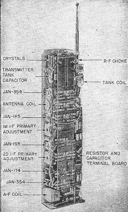
This Handi-Talkie chassis view shows the main components.
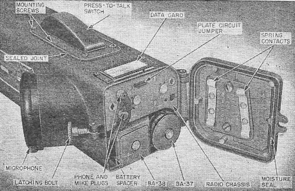
Handi-Talkie antenna switch detail. By Robert F. Scott, W4FSI The Handie-Talkie is perhaps the most widely known and well liked radio set developed during the war. Its efficiency at short ranges and its compactness created a demand for this set in practically all branches of the service. Called by the Signal Corps "Radio Set SCR-536". the Handie-Talkie is built into a metal case 3 5/8 x 5 3/8 x 15 3/4 inches long. This space contains a receiver-transmitter complete with batteries, microphone and ear-phone. Compactly built and weighing but 5 1/2 pounds, it permits the operator to use it like a French type telephone. The SCR-536 is designed for two-way voice communication over distances up to one mile. The effective range is often decreased by terrain features like hills, steel buildings, heavily wooded areas and power lines located between the two stations. On the other hand, the range may be increased by locating the transmitter on the top of a tall building or a hill where the signal will have an unobstructed path to the receiver. Fool-proof net operation is made possible by using crystal control in the receiver and transmitter circuits. This feature permits instant operation by untrained operators who would not be able to make frequency adjustments on other types of sets. These sets may be tuned to practically any predetermined frequency between 3500 and 6000, kc by the selection of proper coil and crystal combinations. Frequency changing in these sets is done by men who have been trained to do this work. Operation is further simplified by the omission of several conventional controls. The only ones on the set are the "on-off" switch and a fingertip operated "push-to-talk" button. The "on-off" switch is mounted inside the set and is operated by the telescoping antenna. When the antenna is fully extended, the switch is thrown on and when retracted, is automatically turned off.
Coils and crystals for changing Handie-Talkie frequencies.
Bottom view of Handie-Talkie. Important features are identified. By careful selection of operating frequencies, these sets may be used in nets with such other sets as the SCR-245 and SCR-193 which employ variable frequency control and may be tuned to the frequency of the SCR-536. How it Operates The receiver portion of the set uses a conventional superheterodyne circuit with a 3S4 r.f. amplifier, a 1R5 oscillator-mixer, 1T4 i.f. amplifier" 1S5 second detector, first a.f. amplifier and a.v.c. A 3S4 audio amplifier supplies approximately 0.18 watt- to a small dynamic earphone. The grid circuit of the r.f. amplifier is tuned by a series combination of the antenna, antenna loading coil and a 0.006-μf fixed mica condenser, as shown in Fig. 1. The plate circuit of this stage is loaded by a permeability-tuned coil and is capacity-coupled to the signal grid of the 1R5. Crystal control of the receiver oscillator frequency is maintained by connecting a quartz crystal between the No.1 grid and screen grids of the 1R5. Excessive oscillator voltage on the signal grid is reduced by a 7-μμf ceramic condenser connected between the signal and oscillator grids. This condenser neutralizes a portion of the oscillator frequency voltage by returning it to the oscillator grid out of phase with the internally coupled voltage. The 1T4 and 1S5 are connected in the standard i.f. and second detector circuits common to most battery receivers. Midget i.f. transformers are used throughout. The secondary winding of the input transformer is loaded with a 1-megohm resistor to broaden the i.f. tuning. Impedance coupling is used in the output circuit to prevent plate current from flowing through the earphone. When the set is in operation, it is a receiver unless the "press-to-talk" button is depressed. A diagram of the complete set is shown in Fig. 2. All switches are in the "receive" position. The Transmitter Circuit When the set is used as a transmitter, switching converts the r.f. amplifier and oscillator-mixer portions of the receiver to a master oscillator-power amplifier transmitting circuit. The first a.f. and power amplifiers of the receiver are converted to microphone amplifier and modulator for the transmitter. While transmitting, the "push-to-talk" button must be depressed. The circuit of the set is then changed to that of the diagram in Fig. 3, and a crystal of a frequency 455 kc. lower than the receiving crystal is switched into the circuit. The output of the oscillator anode is capacity coupled to the grid of the 3S4 r.f. power amplifier. The r.f. tank coil is switched into the circuit and tuned by a 0.00014-μf variable tuning condenser. This combination of coil and condenser is called a "tank" circuit. The antenna loading coil is connected in a pi network tuned by the tank tuning condenser and the capacity existing between the antenna and housing.
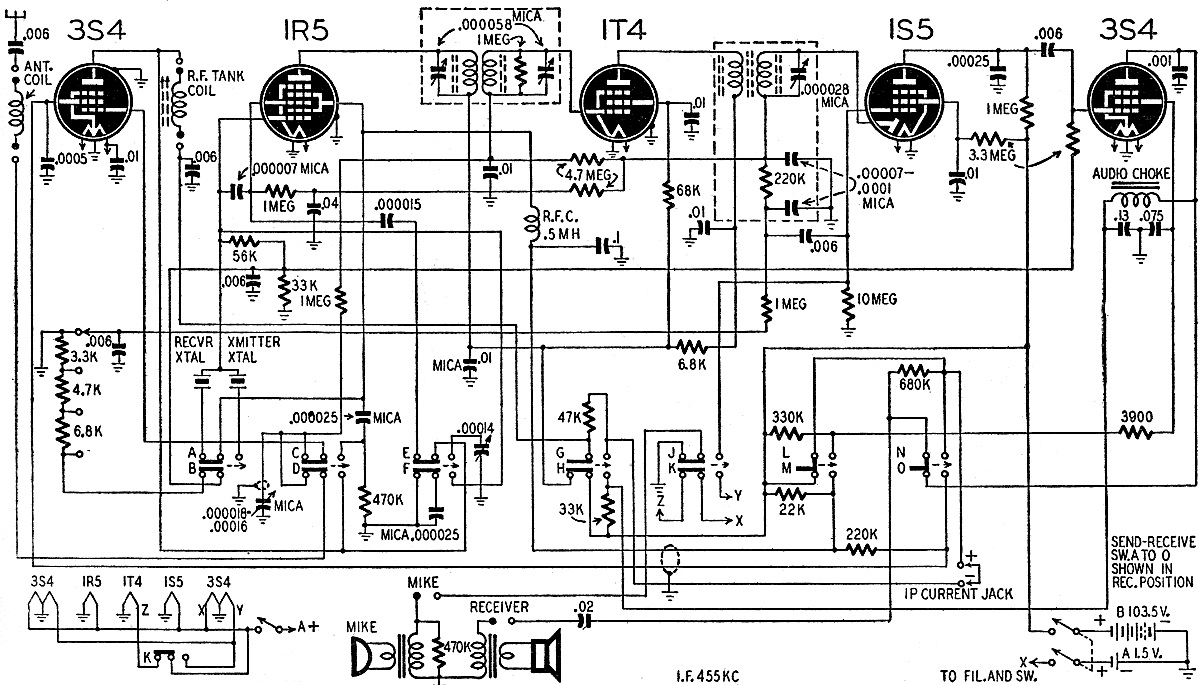
Fig. 1 - Handie-Talkie schematic switched to the "receive" position. Letters refer to switches shown in schematic form in the drawing below. Note that only one side of the two 3S4 filaments are heated when the set is used as a receiver. Tuning is controlled by the oscillator crystal.
Fig. 2 - Schematic of the war's most famous piece of communications equipment - the Handi-Talkie. Made by Galvin Motorola for the Signal Corps, it was used "in the air, on land and on the sea." Each set employs two crystals ground to frequencies 455 kc apart. The 1R5 acts as a Pierce oscillator in both transmitting and receiving circuits. The 14-section changeover switch is lettered to agree with the other two figures. Early Handie-Talkies had crystal earphones, but later ones used the inductor type illustrated in these diagrams.
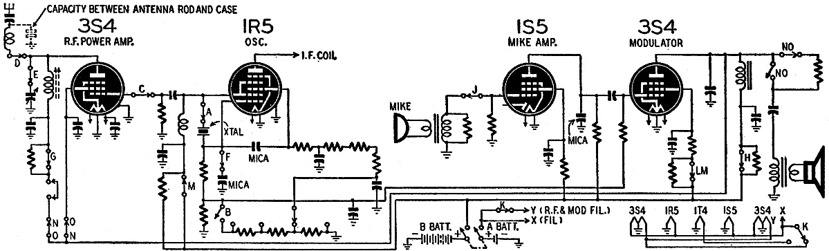
Fig. 3 - As a transmitter, the Handie-Talkie is a four-tube set. The 1R5 functions as master oscillator in a Pierce circuit, driving one of the 3S4's as r.f. power output tube. The 1S5 and the other 3S4 are speech amplifier and modulator, Heising system being used. The dynamic microphone is transformer-coupled to the grid circuit of the 1S5. This tube functions as a speech amplifier and is resistance-coupled to the 3S4 modulator. The grid return of the 3S4 modulator is tapped into the grid leak circuit of the oscillator tube, to provide proper operating bias of the modulator. The a.f. choke in the plate lead serves as the coupling choke for modulation of the power amplifier. A portion of the a.f. output of the modulator is applied to the earphone to provide a sidetone for monitoring transmission. The "push-to-talk" switch is made up of 14 sections, which perform the intricate switching functions which convert the receiver to a transmitter. Each section of the switch has been given a letter to simplify a study of the diagrams. In Fig. 1, all sections of the switch are shown in the receive position. All of the switching functions are evident from the diagrams. Many of the resistors and condensers of this set are mounted in small circular "cups" that fit around the underside of the tube sockets. Terminal lugs are mounted on the rim of the "cups" so that the parts may be connected to the external circuits. Later models abandoned the cup system and used straight terminal strips, as shown in the photo on page 684. The transmitter is easy to adjust. A crystal and plug-in coil for the desired frequency are plugged into the unit and the antenna fully extended. The "push-to-talk" switch is held down and the r.f, amplifier tank condenser adjusted to give minimum amplifier plate current. The plate current is metered by removing a jumper located at the lower end of the chassis. The receiver is tuned by inserting coil and crystal combinations for the desired frequency. The receiver oscillator crystal is ground to a frequency 455 kc higher than the transmitter operating frequency. The receiver is then aligned by conventional methods. Direction Finder, Too
The Handie-Talkie used as a homing device. In the latter days of the war, an accessory was added to the SCR-536 which permitted it to be used for direction finding for locating a command post or unit whose location is not known, or for "homing" in fog or darkness. This is a directional loop antenna used in place of the non-directional telescoping antenna. A modification kit was also provided that permitted the operator to use external headphones. The loop consists of two windings, a single turn secondary winding and a four turn primary winding. The primary of the loop is tuned by a 100-μμf variable condenser. The loop assembly is connected by cable to a matching transformer that matches the impedance of the loop to the input impedance of the receiver. The matching transformer screws to the antenna cap stud and consists of a tuned auto-transformer. Its output lead is equipped with a clip that fastens to the vertical antenna. When the loop and transformer have been tuned to give maximum response from the desired station, the loop is rotated through 360 degrees. There will be two points where the signal strength drops to a sharp null. These points will occur when the loop is broadside .to the direction of the signal source. This will indicate that the signal is coming from one of two directions 180 degrees apart. To determine which is the true direction, a "Sense Button" permits the body to act as a vertical antenna. Rotating the loop 90 degrees in each direction from the null will produce a stronger signal in one direction than in the other. When the loop is turned to the loudest signal, an arrow on its base indicates the true direction. The thumb is then removed from the "Sense Button" and the loop turned to the original null. The operator may then direct himself toward the transmitting station by traveling in a direction perpendicular to the plane of the loop in null position.
Posted October 29, 2021 |
|