FM Carrier Stabilization
|
|
Here is another instance of an article which, if it had been in an April magazine issue, you might be justified in thinking it might be a gag. "FM Carrier Stabilization," a 1946 Radio-Craft feature, centers around the use of a General Electric (GE) GL−2H21 "Phasitron" vacuum tube. Be assured that it is a real component, developed to address the difficulties in achieving frequency modulation (FM) requirements set forth by the Federal Communications Commission (FCC) at what was really the dawn of the FM commercial broadcast radio era. Only a little over a decade had passed since Major Armstrong announced his broadband FM invention, and radio stations were planning to adopt the superior (to AM) form of broadcasting at a rapid rate, following the end of World War II. The Phasitron was GE's solution to the problem of maintaining the average carrier frequency stability requirement. Part I - The General Electric and Federal Systems
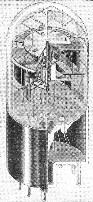
Fig. 1 - The G-E Phasitron, structural view the system of wire deflectors.
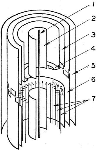
Fig. 4 - Phasitron, cutaway view, 1 - Cathode. 2 - Focus electrode No. 1. 3 - Focus electrode No. 2. 4 - Neutral plane. 5 - Anode No. 2. 6 - Anode No. 1. 7 - Deflector grid.
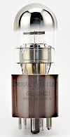
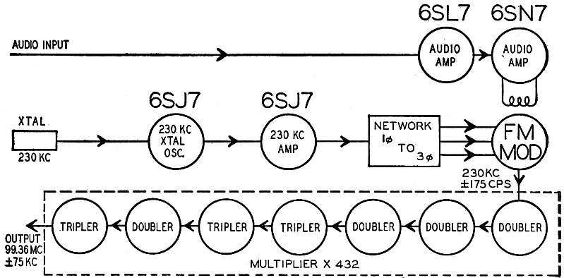
GE GL-2H21 Phasitron (LampesEtTubes) One of the major problems in FM broadcasting has been that of maintaining the average carrier frequency while modulating it so that it deviates up to 75 kc on either side of its assigned value. The FCC regulations call for a maximum drift of only 2000 cycles from the mean, a very small percentage of the new FM carriers (which operate on approximately 100 mc). Amplitude modulation broadcasting takes advantage of the precise unchanging carrier possible with crystal control. This property is a disadvantage in FM. The crystal resists the change of frequency which is the very basis of the system. The major electronic and radio manufacturers have devised ingenious methods whereby the high standard of crystal control is combined with frequency modulation techniques so that the mean transmitted carrier is maintained within the rigid requirements while it deviates in accordance with the modulation to provide the very high fidelity of maximum deviation of which the FM is capable. GE Phasitron Method The type GL-2H21 phasitron tube (Fig 1) is designed to provide wide phase excursions at audio frequency rates in a crystal-controlled carrier. It can operate up to 500 kc. It is generally used at approximately 230 kc, a frequency at which it permits a deviation of approximately 175 cycles per second. Multiplying these values by 432 puts the carrier in the new FM band with a maximum deviation of 75 kc as required.
Fig. 2 - Block diagram of the G-E FM circuit which uses the Phasitron frequency modulator.
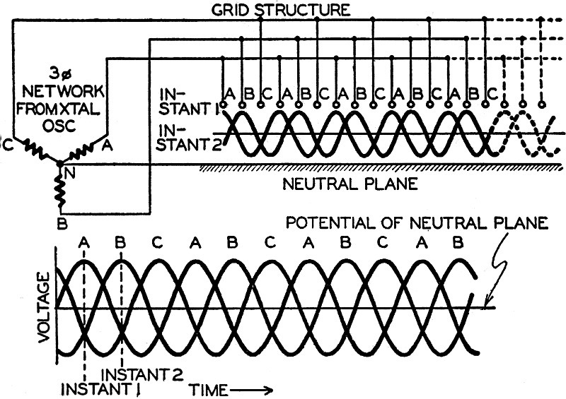
Fig. 3 - Action of three-phase voltage in the deflector grid system.
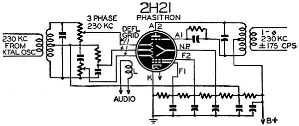
Fig. 5 - How the Phasitron is connected to frequency modulate the crystal's output.
Fig. 7 - Structure of Anode 1 showing maximum and minimum current curves.
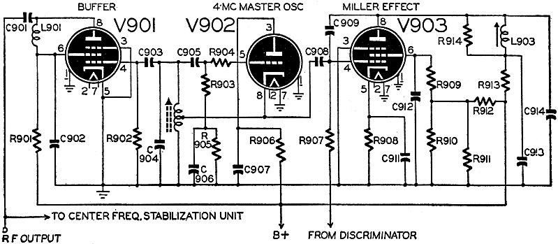
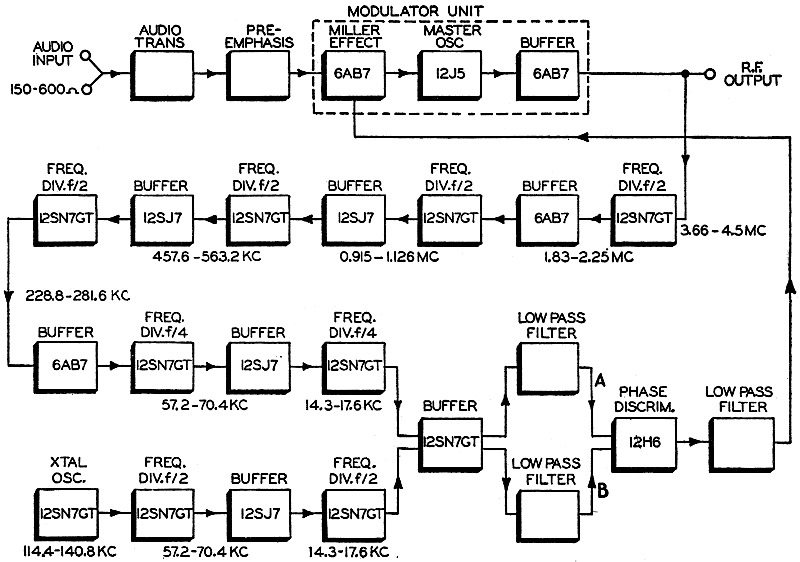
Fig. 9 - The Federal system employs the well-known Miller effect to stabilize frequency.]
Fig. 10 - Block diagram of the stabilizing unit, showing the frequency-dividing system.
Fig. 11 - The 12H6 output corrects frequency. The associated circuits required by the phasitron are not complicated. They consist essentially of a crystal oscillator operating at 230 kc and a circuit to convert the output to 3-phase 230 kc (Fig: 2). The tube contains a deflecting grid structure of 36 wires, the active portions of which are horizontal. Every third wire is connected together and to a common base pin. Each phase of the 3-phase voltage is connected to one of these base pins. An additional deflector is connected to another base pin and constitutes the neutral plane (Fig. 3), and is grounded through a condenser. Electrons emitted from the cathode are attracted to anodes 1 and 2 (Fig. 4), which are at positive potential, thus forming a tapered thin-edge disk. This electron disk extends from cathode to anode 1 and lies between the neutral plane and the system of wire deflectors. Construction of the deflecting grid system and its connection to the circuit are shown in Figs. 4 and 5. As a consequence of the 3-phase voltages, the potentials on grids A, B, and C vary. At some instant, for example, A and B are positive and C negative (Fig. 3-a). The latter grids repel electrons towards the neutral plane, while A and B attract them. The periphery of the disk then assumes a sine wave pattern (Fig. 6) which rotates at a velocity determined by the crystal frequency and the number of deflector grids. Anode 1 has 24 holes punched in it, 12 above the disk plane and 12 below it. These are shown in Fig. 7. At the instant when the sine wave pattern is in the position shown by the heavy lines, all electrons are transmitted through the holes to anode 2. One half-cycle later (dotted lines) no current can pass through the holes and anode 2 current is zero. As the disk rotates the anode current varies sinusoidally between these extremes. To modulate this current a coil L is placed over the phasitron (Fig. 8). It is supplied with the audio frequency current. The magnetic force on each electron moving from the cathode causes the entire disk to rotate in a direction determined by the polarity of the a.f. voltage. This effect acts to speed up or slow down the electrons in the already-rotating disk. Therefore an angular displacement (at an audio rate) is superimposed upon the normal disk rotation due to the 230 kc, 3-phase voltage, and results in phase modulation of the carrier. A maximum a.f. power of 50 milliwatts is required. Federal's Frequency Stabilization
Fig. 6 - Pattern of the rotating disk of electrons due to the three-phase voltage.
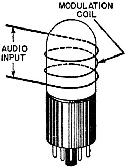
Fig. 8 - How audio-frequency modulation is impressed upon the Phasitron tube. This CFS system is based upon the Miller effect principle, generally known to radio technicians as a difficulty to be overcome. In this case it is a useful property. As a result of Miller effect, the input capacitance of an amplifying tube depends upon its amplification and upon the difference of phase between a.c. grid and plate voltages. The modulating unit (Fig. 9) is an important part of the circuit. It contains a Hartley coupled oscillator operating at approximately 4 mc. This frequency is divided by 256 in suitable multivibrator circuits so that it lies within the limits of 14.3-17.6 kc, depending upon assigned carrier. The frequency of a precise temperature-controlled crystal oscillator is similarly divided so that the frequency is the same as that just mentioned (Fig. 10). The two frequencies so obtained differ in phase. They are passed through a buffer stage and individual low pass filters and then applied to a phase discriminator of the conventional type known to FM technicians and repairmen (Fig. 11). The magnitude of the discriminator a.c. output voltage depends upon the difference of phase between the two applied frequencies A and B. The polarity depends upon whether the Hartley oscillator frequency A drifts upward or down. The low-pass filter which follows the discriminator grounds out the rapid a.f. modulation and permits only the varying voltage caused by gradual frequency drifts to affect the grid bias of the Miller tube (V-903). Change of grid bias of this tube varies the input capacitance and therefore the frequency of the Hartley tank coil across which it is connected. The original frequency drift of the Hartley oscillator is compensated for in this way. The output frequency of the CFS and modulator unit is multiplied in succeeding stages to bring it into the FM band. The center frequency of this transmitter is maintained to within 0.001 per cent of its assigned values.
Posted May 10, 2021 |
|