De Forest the Inventor
|
|||||
When most people are asked to name prolific inventors, people like Thomas Edison and George Westinghouse, with 1084 and 361 each, respectively, come to mind - at least for the United States. As of this writing, Kangguo Cheng of IBM holds the record with 2039 U.S. patents assigned. Nikola Tesla had about 300 patents. Lee de Forest, the subject of this 1937 Radio−Craft article, had a little over 180 patents. That still qualifies as prolific by my estimation. However, there is more to ranking a person's inventive worth than the number of patents awarded - like how profoundly his or her invention(s) impacted the world. For instance, Alexander Graham Bell had a mere 18 patents awarded in only his name, with 12 more shared patents. If you look through Wikipedia's "List of Prolific Inventors," you will see a lot of names with a lot of patents assigned, but most of those names are probably unfamiliar. Notice how many of the old patent art looks like something from a Dr. Seuss kids' book; e.g., Figure 5, "A pneumatic telephone for communication on trains." See the January 1947 Radio−Craft table of contents for more articles on Lee de Forest. De Forest the Inventor
Some of the most interesting patents granted to Dr. Lee de Forest were not in the field of radio. These less well-known inventions cover such diverse fields, as diathermy, talking pictures, photo-electric devices, range finders, television apparatus and airplane instruments. Cautery Device
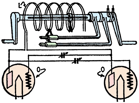
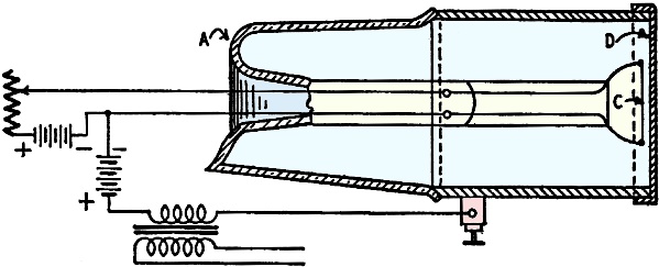
Fig. 1 - A high-frequency surgery patent.
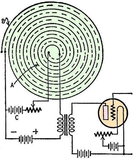
Fig. 2 - A special circuit for diathermy.
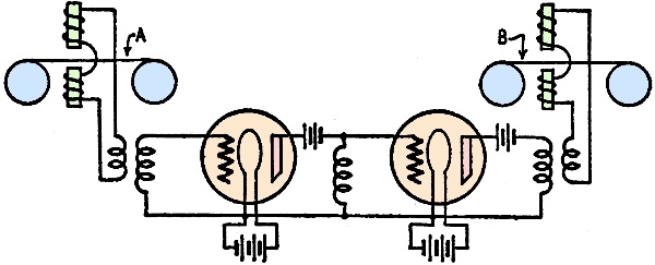
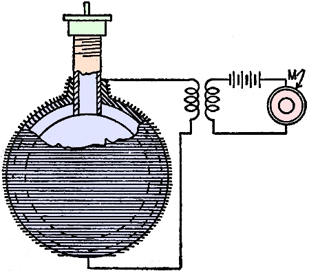
Fig. 3 - Dynamic amplifier without tubes.
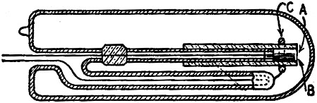
Fig. 4 - Means for reproducing magnetic-wire sound records.
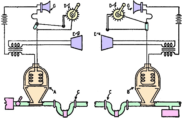
Fig. 5 - A pneumatic telephone for communication on trains.
Fig. 6 - This phonograph pickup works on the thermionic principle.
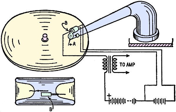
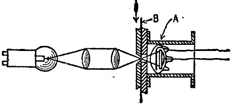
Fig. 7 - A microphone which employs a vibrating mirror and photocell.
Fig. 8 - A gaseous-tube microphone with vibrating anode-diaphragm.
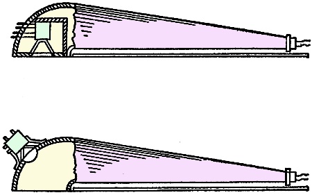
Fig. 9 - A loudspeaker which works on air.
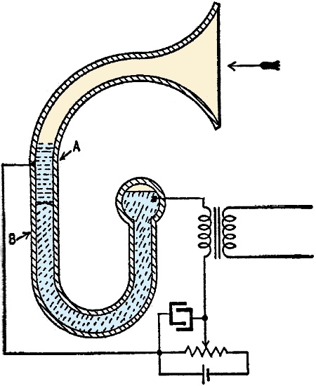
Fig. 10 - Another interesting loudspeaker.
Fig. 11 - Air-blast "very loud" speaker.
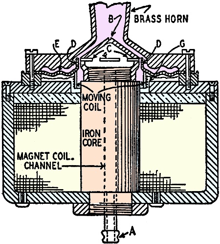
Fig. 12 - Combined horn and cone speaker.
Fig. 13 - Another heat-operated speaker.
Fig. 14 - A unique loudspeaker principle.
Fig. 15 - Sound movie glow-discharge lamp.
Fig. 16 - Another talking-picture lamp.
Fig. 17 - A photocell for sound recording. One of the early de Forest medical patents disclosed an idea for a high frequency cautery device. Patent No. 874,178 was issued on it Dec. 17, 1907. An oscillating or singing arc R (Fig. 1) was the exciter for the cautery electrode. A tuned circuit comprising a condenser C and an inductance I1 is shunted across the arc A; this inductance may be the primary coil of the air-core transformer used to transfer the high-frequency current to the cautery electrode E. E1 is the ground electrode. Frequencies of 500 to 1,000 kc are suggested. Dr. de Forest has experimented considerably in the shortwave diathermy field. His patent No. 2,126,541 provides a unique design for such apparatus. The output or treatment electrodes are excited by vacuum-tube oscillators 0-0 in a circuit tunable from 3 to 13 meters. A coiled Lecher wire system L is used; this gives the advantages of the distributed capacity and inductance of the Lecher system and at the same time greatly reduces the dimensions of the apparatus. See Fig. 2. Tube-less Amplifier A tube-less amplifier of the dynamic type is the unusual device covered in patent No. 1,134,594, dated Apr. 6, 1915. A series of magnetic windings A, B, C, on iron cores are placed in close proximity to a revolving metal disc, similar to the arrangement in a homopolar dynamo. (See Fig. 3.) The signals to be amplified are passed through the several coil windings in progressive order, and as the inventor states, "there is thus provided a means of dynamically amplifying minute current impulses, imparting thereto new energy from a local source ... without moving contacts, microphonic or otherwise ... and without ohmic resistance or resistance-altering devices." A unique invention, to say the least, and worth study by all electrical and radio students. Telegraphone Magnetic wire recorders engaged the attention of de Forest at an early date. Two patents involving the use of such devices are No. 1,375,447, Apr. 19, 1921 and No. 1,177,848, Apr. 4, 1916. The first patent describes means for reproducing sounds from magnetic s records (steel wire recorders). The second covers the procedure for magnetically recording the amplified pulsating current thus produced. The originating wire recorder A may have its steel wire magnetized by sound waves (electric voice currents) in the usual manner. This device permits one to make a duplicate copy B of a telegraph one record. See Fig. 4. Subterranean Signaling System Transmitting and receiving high frequency signals through the earth is proposed in patent No. 1,424,805 (Aug. 8, 1922). The transmitter and receiver are connected to earth through buried metal plates separated quite a distance. The earthed circuit is preferably tuned to the generator frequency by suitable tuning means. Advantage claimed is the freedom from atmospheric disturbances. Pneumatic Telephone The transmission and reception of speech or other sounds, such as telegraph signals, over the air-brake pipe line extending along a train of standard railroad cars, is described in patent No. 1,515,152, Nov. 11, 1924. See Fig. 5. Magnetically controlled air pulsators (A and B) are used to impress the sound vibrations upon the air column in the pipe line C (the air brake and signal lines). Stations are called by means of interrupters D (noise producers). When the engineer or conductor hears a buzzsaw note in the receiver, he knows that he should listen for a message. The sound waves induced in the air line are picked up by the magnetic pulsators, the vibrating air column causing a diaphragm to vibrate and in turn induce electric currents of corresponding frequency in coils placed behind the diaphragm. These voice currents may be amplified, and are connected to a standard type telephone receiver E or loudspeaker. Microphones are marked G. Thermionic Phono Pickup Electric pickups for phonographs have become very popular in recent years. De Forest received an interesting patent - No. 1,554,561 - date Sept. 22, 1925 - for a phono pickup operating on e thermionic principle. The sound vibrations picked up by the needle A in contact with the phonograph record are transmitted to a grid member B sealed into an evacuated glass chamber, as shown in Fig. 6. A heated filament within the tube supplies an ionized field; vibrations of the grid cause corresponding modulation of the current in the circuit connected to the electrodes of the tube. The output of the thermionic pickup may be connected to a vacuum tube amplifier and any desired amplification of the sound readily obtained. The pickup is strongly reminiscent of the Vibrotron, a 1946 tube based on much the same principles. Diffraction Microphone A novel diffraction microphone invented by de Forest Aug. 27, 1929, is described in patent No. 1,726,289. In this device a beam of light is flashed onto a photocell. A polished mirror A is interposed in the path of the beam of light; this mirror is electrically heated. (See Fig. 7). It was found that sound waves striking the heated layers of air in proximity to the mirror caused changes in their diffracting powers and consequent variations or diffraction in the beam of light. In turn these variations in the beam of light are recorded by the photocell B, connected in a telephone or modulator circuit; the pulsations in the voice are thus reproduced in the circuit controlled by the photocell. Gaseous Microphone A noise-free microphone of the gaseous type forms the subject of patent No. 1,834,051 - dated Dec. 1, 1931. The microphone is built into a glass and metal cylinder A, fitted with a flexible gas-tight diaphragm D at one end. See Fig. 8. An electrically heated cathode C is mounted a short distance behind the flexible metal diaphragm. Voice (air) waves striking the diaphragm cause variations in the ionized field between it and the heated cathode, causing fluctuations in the current in the main telephone circuit connected to the microphone. The chamber may be exhausted to a high degree and a slight amount of gas admitted. Loudspeakers De Forest was much interested in loudspeakers. A diaphragm-less loudspeaker is described in patent No. 1,641,664 - Sept. 6, 1927. As Fig. 9 shows, two spirally wound strips, insulated from each other, are connected to the output of an amplifier or other voice current supply. The cathode strip A is heated to provide an ionized field between the two spiral conductors. B is the anode; C is the heating current source. When this field is modulated by the voice current, the surrounding air has sound waves set up in it, in the manner of the speaking arc. The cathode spiral strip may be made of fine woven wire, loaded with certain oxides of the rare earths to intensify the electronic emission. Other patents on loudspeakers include No. 1,560,502 - a means of vibrating a curved loudspeaker member. The actuating device or motor for driving a loudspeaker is the subject of patent No. 1,718,337. A novel cone speaker is illustrated and described in patent No. 1,554,794. Another diaphragm-less type speaker is described in patent No. 1,486,866. A sealed inflated elastic body has wires wound around its exterior surface, which causes it to contract and expand in accordance with the fluctuations of the voice current impressed on the microphone M. See Fig. 10. A table-lamp speaker appears in patent No. 1,452,827 - Apr. 24, 1923, and a cylinder type speaker in patent No. 1,736,035 - Nov. 19, 1929. A novel speaker mechanism designed for controlling the escape of compressed air in accordance with the undulations of the voice current applied to it, is described in patent No. 1,766,612 - June 24, 1930. This speaker is intended for use where powerful sound waves are to be reproduced. The voice coil moves longitudinally in the field of a strong electromagnet, and causes slots in a valve to open and close in exact proportion to the fluctuating strength of the voice current. See Fig. 11. Compressed air is admitted through pipe A which passes clear through the center core of the magnet. The magnet is excited by direct current. A brass dome B is threaded onto the upper end of the magnet core. This dome has slits C cut into it, through which compressed air from the tube A can pass, whenever the sliding sleeve D is moved up and down by the voice coil and uncovers the slits. A corrugated diaphragm E supports the moving voice coil G and the valve sleeve. The compressed air liberated through the slits is in direct proportion to the strength of the varying voice current, thus creating powerful sound waves in the horn attached to the air-valve chamber. A combination cone and horn speaker is described by de Forest in patent No. 1,785,377 - Dec. 16, 1930. See Fig. 12. This combination has been found to reproduce the broad band of voice frequencies more satisfactorily than either speaker alone. Another similar type speaker of large proportions, for use where a great volume of sound is desired is covered by Patent No. 1,853,850. Thermophone A loudspeaker of the diaphragm-less type, operating on the hot-wire or thermophone principle, was invented by de Forest Feb. 17, 1925. See his patent No. 1,526,778 and Fig. 13. A fine wire W is concentrated in an insulating disc D (or at the focus of a parabolic reflector in one form), fitted with a perforated cover through which the sound emerges. The heating effect of undulating voice currents causes the fine wire to expand and contract. These rapid thermal changes are communicated to the adjacent air envelope and set up sound waves therein. One of the advantages of the thermal type speaker is the faithful reproduction of sound. The principle involved is worthy of further study by our engineers intent upon high-fidelity music and speech reproduction. An unusual scientific principle is involved in a loudspeaker (or microphone) covered by patent No. 1,738,988. It utilizes variations in the capillary boundary between two liquids of differing densities. See Fig. 14. With mercury and dilute acid, for example, placed in a capillary tube, a meniscus or semi-globular surface forms between them. If a varying (voice) current is applied to such a tube through suitable electrodes making contact with the acid A and the mercury, B, the current will cause the contact surface or meniscus, C, between the two liquids to rise and fall within the tube. This action in turn will create sound waves in the acoustic horn chamber shown in the picture. This is the loudspeaker action. When used as a microphone the reverse action occurs ... the sound waves strike the liquids in the capillary tube and cause the meniscus to rise and fall. If an electric current is connected to the tube terminals, variations corresponding to the voice fluctuations in this current will be created (in the external circuit). A loudspeaker connected in this circuit will reproduce the sounds originating at the capillary microphone. Talking Pictures Dr. de Forest performed a great deal of research on devices to improve the early talking pictures. An early patent, No. 1,482,119, Jan. 29, 1924 - describes a method for recording the picture and the voice record on the same film simultaneously. An early arrangement used an arc for recording the voice patterns on the film. Some more stable form of glow discharge was desirable, and one of de Forest's designs for a glow tube that could be modulated by the voice current, is covered in patents No. 1,806,746, May 26, 1931, and No. 1,873,558, Aug. 23, 1932. See Figs. 15 and 16. The glow or corona A was concentrated at one end of the tube and was of high intensity. The voice current, when super-imposed on the electrodes B and C of the glow tube, caused the intensity to vary. Binaural recording and reproduction of sound is interestingly described in patent No. 1,769,907 of July 1, 1930. This has to do with speakers placed in different parts of the theater, each speaker reproducing certain frequencies and thus giving a third-dimension sound effect. Photo-Electric Cell An improved photocell was devised and patented by de Forest, July 30, 1929 (Patent No. 1,722,280). See Fig. 17. The light-sensitive cell A is made in a flattened lenticular shape so that the electrodes within the cell will be located only a short distance from the film B on which the sound track is impressed. A steady source of light projects a beam of light through the film sound track upon the photo-cell. Television One of the earliest television patents of de Forest, No. 2,003,680 was issued June 4, 1935. It describes a television receiving and projecting method for scanning a strip of specially prepared film and electrically etching pictures thereon. Patent 2,026,872, issued in 1936, describes a means of producing a large size television image. The received image is recorded on specially treated film and may be later projected onto a screen by the usual projector. Sound is reproduced by a sound track recorded on the picture film at the same time the picture signals are recorded. An ingenious method for recording or etching the picture images on the coated film by an electrostatic discharge is described. The discharge is modulated by the received television signals. A following patent covers further developments of this idea and includes means for synchronizing the received images with the accompanying sound signals. An idea for stereoscopic television is covered by patent 2,163,749. Radial scanning is one of the features here proposed. A cathode beam radial scanning system appears in patent 2,241,809 issued May 13, 1941. The cathode beam is deflected back and forth by a rotating switching device; thus the beam traverses a non-repeating pattern on the screen. Television Sign A television sign is described in patent No. 2,049,763 dated August 4, 1936. In the future we shall undoubtedly see many signs of this type along our highways. It is operated by remote control from a television station. A salient feature of this television sign is that practically any picture can be reproduced on its face, either in silhouette or halftone effect. The glow lamps on the surface of the sign are controlled by a switch directed by television signals, which may be picked up by a television receiver located near the sign. These signs may be operated out in the open country and a number of signs can be controlled at the same time from one transmitter. The patent describes the preferred form of the high-voltage glow tubes and the switching mechanism. In one suggested form the sign might contain a hundred rows of glow tubes, with a hundred tubes in each row. Ten thousand glow tubes would be used in this case and thus a very good reproduction of the image realized. High voltage is fed to each glow tube as the commutator switch makes the proper connection, in accordance with the television signal directing it. Many of the above inventions were not followed up, for one reason or another: They offer challenging opportunities for the engineer or experimenter today. Certain speakers, for instance, were not practical when 90 volts of B battery was a standard power supply but might be quite usable now that 450 or even 900 volts can be obtained if desired. These patents are worth study.
Posted April 3, 2024
|
|||||

 by H. Winfield Secor