The Square-Corner Reflector Beam Antenna for Ultra High Frequencies |
|
The Square-Corner Reflector Beam Antenna for Ultra High Frequencies By John D. Kraus, W8JK
Fig. 1 - A radiator with a parabolic reflector is shown at A. A radiator with a "corner" reflector is shown in perspective at B and in cross-section at C.
Fig. 2 - Horizontal square-corner reflector antenna with grid-type reflector. Here is an antenna system particularly suited to u.h.f. work that combines considerable gain with no necessity for critical adjustment and tuning. It has a gain approaching 10 db over a single half-wave antenna, can be either horizontally or vertically polarized, and can be folded for transportation when used for portable work. The small physical size of ultra-high-frequency antennas makes many designs practical which are not feasible to build on lower frequen-cies. The sheet reflector is an antenna of this type. Sheets in the shape of a section of a parabolic cylinder have often been used. Fig. 1-A shows such a reflector with a driven radiator situated at the focus, one of the first directive types of antennas ever tried. The parabolic reflector antennas are analogous to the parabolic reflectors or mirrors used in optical systems. If the parabolic reflector is sufficiently large, so that the distance from the focus to the reflector is many wavelengths, optical conditions are approached. However, if the reflector is of the same order of dimensions as the operating wavelength, or less, the analogy to optics is not complete, since the driven radiator is appreciably coupled to the reflecting sheet. Another type of reflector, which forms a very practical and effective system, consists of two flat conducting sheets which intersect at an angle so as to form a corner. This system has been termed a "corner" reflector antenna.1, 2 Fig. 1-B is a perspective view of a typical corner reflector antenna. The same antenna is shown in cross-section in Fig. 1-C. If the driven radiator is situated on the line bisecting the corner angle, as shown, the maximum radiation is also in the direction of this line. There is no focus point for the driven radiator as with a parabolic reflector, and the radiator can be placed at a variety of positions along the bisecting line. Because of the shape of the reflector, it might also be appropriately referred to as a "V" reflector or a "sphenoidal" (wedge-shaped) reflector. An advantage of the sheet reflector is that, if the sheet is sufficiently large, its dimensions are not critical as to frequency. Hence, the reflector can be put into operation without the need for any tuning adjustments. The corner reflector antenna is particularly suitable for use on the higher frequencies where structures one or two wavelengths in maximum dimensions are practical to build. Tests indicate that parabolic reflectors of this size have no particular advantage in performance over the corner type. On the other hand, the corner type has the advantage of being simpler to construct. The reflecting sides are flat and are readily adapted to a folding structure for portable work. The corner reflector antenna constitutes a distinct type of antenna system having unique properties and characteristics which make it especially suitable for use as a beam antenna on the ultra-high-frequencies. The two sheet reflectors of the corner antenna may be arranged to intersect at a variety of angles. When the sheets intersect at right-angles, the system is referred to as a "square-corner" reflector.1 Corner angles larger than 90° can be used, with some decrease in gain. A 180° "corner" is equivalent to a single flat sheet reflector, and this may be regarded as a limiting case of the corner type of reflector. The application of a single flat sheet reflector to a directional system has been discussed by George H. Brown.3 Corner reflectors with angles smaller than 90° are also practical. Theoretically, the gain increases as the corner angle is decreased. However, to fully realize this gain it is necessary that the size of the reflecting sheets also be increased. For a structure of the smallest size consistent with a substantial power gain and high directivity, the 90° corner offers a practical compromise. Accordingly a square-corner reflector will be described which is especially suitable for amateur use on the ultra-high-frequencies. Instead of employing solid sheets, a very practical arrangement is to use a number of parallel wires or conductors to simulate the reflecting sheet. Fig. 2 is a perspective drawing of a square-corner antenna with a grid-type reflector. The parallel conductor arrangement is cheaper, more effective, and presents relatively little wind resistance as compared to solid sheet or many screen-type reflectors. For these reasons, the grid-type reflector is recommended. Construction and Dimensions
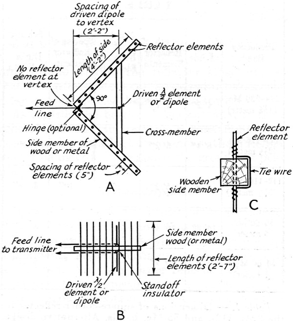
Fig. 3 - Construction of a square-corner reflector antenna with grid-type reflector. With the antenna vertical, A is the top view and B the side view. With the antenna horizontal, A is the side view and B the top.
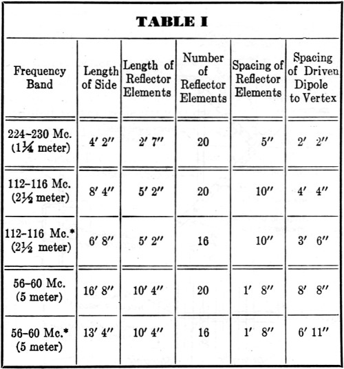
Table 1. - Dimensions of square-corner reflector for the 224-, 112-, and 56-Mc. bands. Alternative designs are listed for the 112- and 56-Mc. bands. These designs, marked (*), have fewer reflector elements and shorter sides, but the effectiveness is only slightly reduced. There is no reflector element at the vertex in any of the designs. The construction is shown in Fig. 3.
Fig. 4 - Method of mounting a square-corner reflector for horizontal operation (A), and for vertical operation (B). Fig. 3 shows the construction for a square-corner reflector with dimensions for the 224- to 230-Mc. band (1 1/4-meter band). The dimensions for this band are also listed in Table I, which, in addition, gives dimensions for the 112- and 56-Mc. bands. The dimensions for the 112-Mc. antenna are twice, and the 56-Mc. antenna four times those for the 224-Mc. antenna. Furthermore, alternative dimensions are given for 112-Mc. and 56-Mc. square-corner reflectors of somewhat smaller overall dimensions. These are suitable where the bigger reflectors would be inconveniently large. The decrease in size causes only a slight reduction in performance. As shown in Fig. 3, the main supporting structure for the reflector is an A-shaped frame. The two sides of this"A" frame are about one wavelength long and are joined at right angles at the vertex. These side members carry the reflector elements. A cross-member joins the two side members and carries the driven element or radiator. The distance between the driven radiator and the vertex, or corner, is not critical and can be varied over rather wide limits with little change in the directivity of the antenna. Especially suitable values are between 0.35 and 0.5 wavelength. A value of 0.5 wavelength is recommended for the antenna described. This amounts to 26 inches for the 224-Mc. antenna. At a spacing of 0.5 wavelength from the driven dipole to the vertex, the radiation resistance of the driven dipole is a maximum. It is, in fact, almost twice the radiation resistance of the same driven dipole when alone in free space. Under these conditions the effect of losses in both the driven dipole and the reflector is minimized, making for maximum radiation efficiency. In order to realize the full benefit of this high radiation resistance, the use of a closely-spaced director with a corner reflector system is not recommended. However, a few directors spaced at intervals of 3/8 wavelength can be used to advantage. This high radiation resistance is an important advantage of the corner reflector over the close-spaced 3- or 4-element beam in which the low feed point resistance is a limiting factor to the efficiency. Smaller spacings of driven dipole and vertex are entirely practical, but at a slight sacrifice in efficiency. The alternative design for the 112- and 56-Mc. square-corner reflector in Table I has a dipole-to-vertex spacing of 0.4 wavelength. At this spacing the driven dipole radiation resistance is still somewhat higher than its free space value, but is considerably less than when the spacing is 0.5 wavelength. The driven dipole is situated at the mid-point of the cross-member so that it is equidistant from the two planes of reflector elements. The side member, which supports the reflector elements may be of either wood or metal, there being no appreciable difference in operation whether the mid-points of the reflector elements are electrically connected or not. The reflector wires should be No. 12, No. 10, or larger diameter. For the 224-Mc. reflector, No. 12 or 10 wire is sufficiently stiff to be self-supporting. For the 112- or 56-Mc. bands, heavier wire or tubing may be required. A satisfactory method of securing the reflector conductors to the supporting structure is shown in Fig. 3-C. Holes are drilled for the reflector elements along the wooden supporting member. After the conductors are in place they are fastened by a tie wire. If portable operation is contemplated, a hinge may be installed at the corner to join the side members as in Fig. 3-A. The cross-member carrying the driven dipole is held in place by clamps so that this member can then be removed and the reflector folded flat. Additional hinges can be located mid-way along the side members so that the reflector can be folded into a still more compact form. Instead of fastening the reflector elements in place as indicated in Fig. 3-C, they can be held by fuse clips mounted on the" A" frame. With this construction, all of the reflector elements are easily removed and can be tied in a bundle for transport. The reflector elements are about 0.6 wavelength long. Their length is not at all critical, slight increases or decreases in length producing no noticeable difference in performance. This means that the performance of the reflector is substantially uniform over a wide frequency band. Multi-Band Operation Not only is the reflector effective on the band for which it is designed but also on all higher frequencies as well. The reflector is, thus, suitable for multi-band operation. A square-corner reflector designed for the 56-Mc. band can be used effectively on both the 112- and 224-Mc. bands with no change required in the reflector. Some improvement may, however, be obtained on the higher frequency bands by adding more reflector elements between those already in use so that the spacing does not exceed about 0.1 wavelength between elements on the highest frequency used. On the lower frequencies, the closer spacing of the reflector elements produce very little difference in performance. If anything it results in a slight improvement. In multi-band operation with the same reflector, different driven dipoles are employed for each band, with the spacing to the vertex adjusted to approximately 0.5 wavelength on the band being used. Frame Construction A style of construction different than the one described for the corner reflector is to support the ends rather than the mid-points of the reflector elements. This type of construction requires two rectangular wooden frames, one for each reflecting plane. These frames can be similar in construction to the frames for ordinary window screens. The length of the frame is made equal to the side length given in Table I, and the width equal to the reflector element length. Although somewhat heavier and bulkier, this construction is an entirely practical one. The first tests on a corner reflector at W8JK were made with a reflector supported on a wooden frame of this type.1 No. 12 or No. 10 wire can be used for the reflector elements. The wires are secured to the frame by means of nails or screws. Painting or varnishing of the frame is desirable. The wires of the reflector curtain are not electrically connected at any point.
Fig. 5 - Driven dipoles for use with a square-corner reflector.
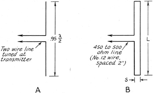
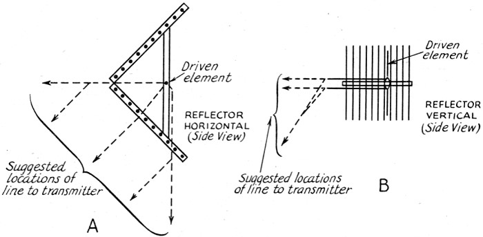
Fig. 6 - Possible ways of leading the feed line from the driven dipole to the transmitter with antenna horizontal (A) or vertical (B). The corner reflector antenna is suited for the transmission or reception of either vertically or horizontally polarized waves. For vertical polarization Fig. 3-A represents the top view of the antenna, and Fig. 3-B, the side view. For horizontal polarization, the driven dipole and reflector are turned horizontal, and Fig. 3-A then represents the side view and Fig. 3-B the top view of the antenna. Whether horizontal or vertical polarization is used is largely a matter of individual preference. However, it is generally desirable to use the same type of polarization for both transmitting and receiving unless, due to reflections over some particular path, tests indicate that different polarization at the transmitter and receiver is preferable. For horizontal operation a practical method for supporting the entire antenna is shown in Fig. 4-A. An extension of the cross-member of the antenna frame is fastened to a mast. In the case of vertical polarization, the mast can be fastened to an additional member placed between the cross-member of the frame and the corner, as shown in Fig.4-B. Another method of support, suitable for either vertical or horizontal operation, is by means of rope bridles tied to the reflector structure, so that the entire system can be pulled up alongside a tower or supported between two towers. As regards the height of the antenna, it is in general true that to transmit the maximum distance on the ultra-high-frequencies, the antenna should be placed as far above the ground as possible. Driven Dipole Once constructed, no adjustments are necessary on the corner reflector. This is an important advantage over antennas which require tune-up adjustments before maximum performance can be realized. With the corner reflector, it is only necessary that adjustments be made on the driven dipole to obtain maximum input to this radiator. The type of driven radiator used with a corner reflector is largely a matter of individual preference. A wide variety of driven dipoles having coaxial or open-wire feed can be used successfully. Two systems using open-wire feed are shown in Fig. 5. If the distance between the antenna and transmitter is relatively short, such as 1 or 2 wavelengths, a tuned line is satisfactory for feeding the center of a single conductor half-wave dipole as shown in Fig. 5-A. The dipole length is computed in the usual manner, being 5 or 6 per cent less than a free-space half-wave. If the distance from the antenna to the transmitter is somewhat greater, such as two or more wavelengths, a matched impedance feed is more satisfactory. An arrangement of this type is shown in Fig. 5-B, the driven radiator being a 2-wire half-wave dipole.4, 5, 6 Carter5 refers to a radiator of this type as a "folded dipole." Dimensions for a 224-Mc. 2-wire dipole are: length (L) = 25 inches spacing (S) = 1 inch.
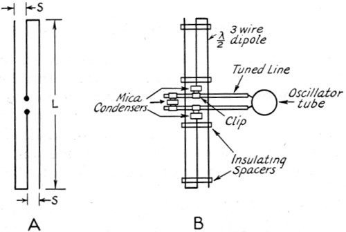
Fig. 7 - 3-wire half-wave dipole (A) and method of mounting to tuned-line transmitter (B).
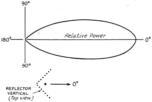
Fig. 8 - Measure horizontal directional pattern for a vertical 224-Mc. square-corner reflector antenna of the type described. For the 112-Mc. band, these dimensions (both length and spacing) are doubled and for the 56-Mc. band, the dimensions are multiplied by four. Both wires are the same diameter. No. 12 or 10 wire is satisfactory for a 224-Mc. dipole. Larger wire or tubing can be used on 112 and 56 Mc. A transmission line of 450 to 500 ohms characteristic impedance (No. 12 wire spaced 2 inches) is used to feed the dipole. This line can be coupled to the transmitter tank circuit by a coil of one or more turns. The coil should be arranged symmetrically with respect to the transmitter tank. Several possible locations for the transmission line are shown in Fig. 6. The locations in Fig. 6-A are suitable when the antenna is horizontal and the paths in Fig. 6-B when the antenna is vertical. Inside of the reflector, the transmission line should be kept substantially in the plane of the supporting members, or "A" frame. The line should be supported as symmetrically as possible and sharp bends should be avoided. If the distance between the antenna and the transmitting equipment is many wavelengths, it may be advantageous to locate the transmitter at the antenna with filament and modulated plate voltages supplied by a 3- or 4-wire cable. This arrangement is well suited for use with low-power equipment on 112 and 224 Mc. where simple oscillator transmitters are permitted. The oscillator tube and associated circuits are placed in a weatherproof box with the antenna protruding. An antenna especially suited for use with this kind of an installation is the 3-wire half-wave dipole.4(B, C) The terminal resistance is relatively high and the antenna can be directly connected to the oscillator circuit, no transmission line being use? A 3-wire dipole is illustrated in Fig. 7-A, while Fig. 7-B shows a tuned-line oscillator with the terminals of a 3-wire dipole connected by clips to the line. The point of attachment may be adjusted for maximum power transfer to the antenna. A pair of condensers (mica 0.002 μfd.) between the antenna terminals and the clips keeps d.c. voltages from reaching the antenna. The same size wire is used for each of the 3 wires of the dipole. A 224-Mc. 3-wire dipole has a length, L, of 24 inches and a spacing, S, between adjacent wires of 0.5 inch. For the 112-Mc. band these dimensions are doubled. The power cable supplying the transmitter should be arranged to follow a path similar to one of those suggested for the transmission line in Fig. 6. There is no appreciable difference in the directivity of a 2- or 3-wire half-wave dipole. When used with a square-corner reflector, the 2-wire is better suited for use with a transmission line and the 3-wire with the transmitter at the antenna. In addition to the systems described, in which the antenna is fed at the center, end-fed antennas can also be used. End feed is best adapted to vertical antennas, the feed point being the lower end. Any of the common types of end feed, such as the "J" stub type, can be used. Performance Tests have been made on many types of corner reflector antennas at W8JK. The measured directional pattern of a 224-Mc. square-corner reflector is shown in Fig. 8. The antenna is vertical and the pattern is in the horizontal plane. The construction is as shown in Fig. 3. The dimensions are approximately the same as given in Table I A 3-wire half-wave driven dipole is used with the transmitter located at the dipole as in Fig. 7-B. The measured front-to-side and front-to-back ratios are high, 25 db for the front-to-side and 35 db for the front-to-back ratio. At an angle of 10° from the center line of the beam, the signal is 1 db down; at 20° 3 db, 30° 6 db, 40° 10 db, 50° 16 db, 90° 25 db and 180° 35 db down. The directional pattern is very smooth, being free from minor lobes of any appreciable size. The power gain of the antenna approaches 10 db over a comparison half-wave dipole in free space with the same power input. In conclusion, it may be said that the square-corner reflector gives a large power gain, high directivity, and is capable of excellent performance as a beam antenna on the ultra-high-frequencies. 1 J D. Kraus, "The Square-Corner Reflector," Radio, March, 1939. 2 J. D. Kraus, "The Corner Reflector," Proc. I.R.E., Sept., 1939, p. 613 (abstract of paper given at N. Y. C. Convention of I. R. E., Sept., 1939. 3 G. H. Brown, "Directional Antennas," Proc. I.R.E., Jan., 1937, p. 122. 4 (A) J. D. Kraus, "Multi-wire Doublet Antennas," Radio, May, 1939, p. 24; (B) "Multi-wire Type Antennas," Radio, June, 1939, p, 21; and (C) "Multi-wire Dipole Antennas," Electronics, Jan., 1940, p. 26. 5 P. S. Carter, "Simple Television Antennas," RCA Review, Oct., 1939, p, 177. 6 J. D. Kraus and S. S. Sturgeon, "The T-Matched Antenna," QST, Sept., 1940, p. 25.
Posted April 6, 2016 |
|