Magnetostriction Devices and Mechanical Filters for Radio Frequencies |
|
If you have ever heard the audible hum emitted by a power supply transformer, then you are familiar with at least one of the manifestations of magnetostrictive materials. I thought maybe shape memory metals ("muscle wire") would be considered magnetostrictive, but research shows they are classified separately because their shape change is attributed primarily to heating rather than magnetization. I also thought the old 'reeds' type receive decoders for pre-1960s-era radio control systems might be magnetostrictive devices, but no search turned up anything where the term was used. This article and its two succeeding articles discuss magnetostrictive filters at kilohertz IF frequencies. Part I covers the fundamentals of magnetostrictivity while Part II gets into building realizable bandpass filters. Unfortunately, I do not have the August 1953 edition of QST for Part III. The referenced article in the September, 1950, issue of the RCA Review was located on the American Radio History website, for those wanting to know more about the subject. Magnetostriction Devices and Mechanical Filters for Radio Frequencies Part I - Magnetostriction Resonators (see Part II) By Walter Van B. Roberts, W2CHO Recent developments in the field of mechanical resonators may foreshadow increasing applications in our amateur gear, especially in high-selectivity receivers and single-sideband filters. This is a "get-acquainted" article, outlining the principles of magnetostrictive and mechanical resonators and showing how they are applied. There is plenty in this and in subsequent parts of this article to whet the experimenter's appetite - especially since some of the currently hard-to-get materials may be more readily available in the near future.
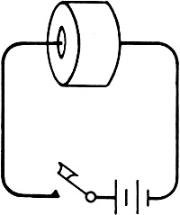
Fig. 1 - Form of length vs. magnetization curve for nickel. Iron is, of course, the most commonly used magnetic material. But nickel is also strongly magnetic, as is easily seen by the way it sticks to a magnet. In addition, nickel is relatively strongly magnetostrictive; that is, the length of a piece of nickel will change when it is magnetized. The actual amount of change is very small, not over one part in 20,000, but even this small amount is large compared with what is found in most magnetic materials, and is sufficient to be put to practical use. Fig. 1 shows how the length of a piece of nickel wire varies with its magnetization. The same sort of curve applies to other magnetostrictive materials, except that the amount of change is usually much smaller and some materials lengthen instead of shrinking when magnetized. Fig. 2 shows how mechanical vibrations can be produced in a nickel wire by means of magnetostriction. The permanent magnet is placed near enough to the wire to cause it to shrink about half the maximum possible amount. Then when current flows in the coil it will either decrease or further increase the amount of shrinkage, depending on whether the magnetizing effect of the coil opposes or aids the field of the magnet. If the current is alternating, the length of the wire will vary at the frequency of the current. The constant field of the magnet will be called the magnetic bias, and the field of the coil will be called the driving field. (The bias could also be produced by a d.c. component of current in the coil, or by permanent magnetization of the nickel.) Thus, the magnetic bias and the driving field correspond somewhat to the voltage bias and signal voltage on the grid of an amplifier tube. If the frequency of the driving field is not near the natural frequency of vibration of the wire, the variation in the wire length will be extremely small, but if the piece of wire in Fig. 2 is one inch long and the frequency of the driving current is about 100 kc., a much greater amplitude of vibration occurs. The one-inch length of wire has a natural frequency of longitudinal vibration at about 100 kc. When the driving-current frequency is made to match the mechanical resonance of the wire, considerable mechanical power is transferred to the wire and the vibration of the wire reacts upon the driving coil just as though the wire were a sharply tuned electrical circuit loosely coupled to the driving coil. This reaction can be observed by connecting the driving coil to a Q-meter. Then when the frequency of the Q-meter is slowly shifted through the resonant frequency of the wire, the apparent Q of the coil takes a sharp dip. The sharpness of the dip depends on the mechanical Q of the wire resonator.
Fig. 2 - Longitudinal type magnetostriction resonator.
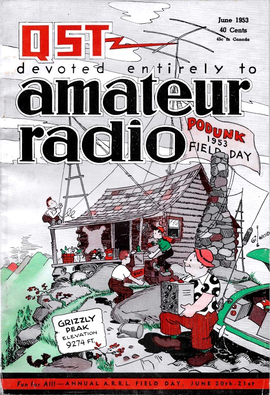
Fig. 3 - Q-meter response as the driving frequency to a pair of coupled circuits, both tuned to the same frequency, fo is varied. The peak separation increases with the coefficient of coupling. The term "mechanical Q," as applied to a mechanical resonator, means the number of cycles of vibration required for the amplitude to die down to 4.32 per cent of its original amplitude after the driving force is removed. (This same definition applies to the Q of a tuned circuit). In general, the Q of a mechanical resonator is much higher than that of the best tuned circuits and this is one of the great advantages of mechanical resonators. Ferrite Resonators The use of nickel and other metal rod resonators in the manner illustrated in Fig. 2 is nothing new, but has not been very widespread because resonator materials known heretofore have been metallic and hence cause large eddy current losses which spoil the Q of the driving coil. Also, the mechanical Q of a nickel resonator is only a few hundred. (Many metals have mechanical Qs up to ten thousand, but are not magnetostrictive). There has recently become available, however, a new group of magnetic materials, called ferrites, that are much better adapted to magnetostrictive resonator use. Ferrites are more in the nature of ceramics than metals, and may have high electrical resistivity so that eddy-current losses are negligible. Their mechanical Q is of the order of several thousand, and some are strongly magnetostrictive. Their permeability is usually high and when a ferrite resonator is put in a coil it may greatly increase the Q of the coil itself. The longitudinal vibration frequency of a ferrite rod is about 103 kc, divided by the length of the rod in inches. Ferrites are made by mixing powdered Fe2O3 with various proportions of other metallic oxides, pressing to the desired shape, and firing at 1300 to 1400 degrees C. The mix can also be extruded in the form of rods or tubes. After firing, it is too hard and brittle to machine. It can be ground or cut with a diamond saw. The permeability, magnetostrictive activity, and improvement of coil Q are determined by the proportions of the oxides forming the ferrite. No one composition makes all these quantities maximum; the composition to use depends upon the job it has to do. A good magnetostrictive ferrite can be made of "equimolar" proportions of iron and nickel oxides; i.e., 159.68 grams of Fe2O3 and 74.69 grams of NiO. More detailed information about ferrites may be found in the September, 1950, issue of the RCA Review. Coefficient of Coupling
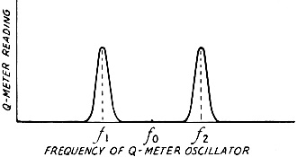
Fig. 4 - Set-up for measuring the coefficient of coupling between a tuned circuit and a ferrite-rod magnetostriction resonator.
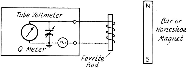
Fig. 5 - The equivalent circuit, B, of a magnetostriction resonator coupled to a coil. When two electrical circuits of low losses are tuned to the same frequency (f0) and coupled together, two resonant frequencies are found in the system. For example, if one of the circuits consists of a coil and the variable condenser of a Q-meter, then as the frequency of the Q-meter is varied, two peaks of the meter will occur as shown in Fig. 3. If the second circuit is sufficiently low-loss, the coefficient of coupling between the two circuits is given by (f2 - f1) / f0. Now let the second circuit be removed and a ferrite resonator (suitably magnetically biased) put in the first coil, as shown in Fig. 4. With the coil tuned to the same frequency (f0) as the resonator, the Q-meter will behave exactly as before. Hence, the quantity (f2 - f1) / f0 may be defined as the coefficient of coupling between the coil and the ferrite. This quantity is a more useful measure of the magnetostrictive activity of the material for circuit calculations than the "magnetostrictive coefficient," which merely gives the amount of stretch or shrink in length that can be produced by magnetizing. The coefficient of coupling can be decreased by removing the resonator more or less from the coil or by decreasing the bias, but cannot be increased beyond an upper limit determined by the nature of the material. This limit is of the order of 10 per cent for ordinary coils and ferrites made for good magnetostriction. From the coefficient of coupling it is easy to show that a coil with a ferrite resonator in it (Fig. 5A) is equivalent to Fig. 5B. Here L is the inductance measured at a frequency far from the ferrite resonance and k is the coefficient of coupling measured as described above. The condenser and resistor give the equivalent circuit the same frequency and Q as the ferrite resonator. Ferrite Oscillator
Fig. 6 - Magnetostriction oscillator using a ferrite rod.
Fig. 7 - Method of permanently magnetizing a ferrite torus. Probably the simplest use of a ferrite resonator is as the frequency control element of an oscillator. Fig. 6 shows a suitable circuit. In the absence of vibration of the resonator there is nothing but inductive reactance between P and ground, and therefore oscillations cannot occur. Just above the resonant frequency of the ferrite, however, the total effective reactance between P and ground is capacitive (see Fig. 5B). The circuit will then oscillate if L and C are tuned to the approximate frequency of the ferrite - that is, provided there are not too few turns on the ferrite coil, the tube transconductance and coil Q are not too low, and the coefficient of coupling between the ferrite and its driving coil is not too small. The cathode resistor provides initial grid bias which makes oscillation start more easily. The magnetic bias not only affects the ease of starting but will also be found to have some control over the frequency of oscillation, perhaps to the extent of a per cent in some cases. With this circuit, oscillations should be obtainable up to a few hundred kc., using a 6J6 tube running about 2 mils plate current per plate, even with the ferrite driving coil reduced to a very few turns. Permanent Bias A rod of steel or nickel can be permanently magnetized so that it becomes a bar magnet with north and south poles at its ends. Rods of cobalt ferrite can similarly be permanently magnetized. Unfortunately, however, the kind of ferrite that has good magnetostrictive action is demagnetized so easily that the poles at its end, created by magnetizing the rod, act to demagnetize it as soon as the magnetizing field is removed. This drawback does not occur when there are no poles developed by magnetizing. For example, if a ferrite torus (or any piece of ferrite with a hole in it) has a wire passed through the hole and connected briefly to a battery of 1 1/2 to 6 volts, as shown in Fig. 7, the ferrite will be magnetized with closed loops of magnetic flux linking the wire. No free poles are produced so the magnetization remains and can be used as permanent bias for resonator operation in the modes of vibration that require a bias of this sort. To produce permanent circular bias by means of a flash of current requires that the ferrite have a hole in it. However, it is possible to produce a certain amount of "circular bias" in a solid piece of ferrite by means of magnets, as shown in Fig. 8. Here two horseshoe magnets are put together except for a gap that is considerably smaller than the ferrite to be magnetized. The ferrite is placed against the gap as shown, then moved away. As a result of the easy saturation of ferrite, a small permanent circular bias remains. However, it is much better to use the current method if there is a hole in the ferrite with closed loops of magnetic flux linking the wire. No free poles are produced so the magnetization remains and can be used as permanent bias for resonator operation in the modes of vibration that require a bias of this sort. To produce permanent circular bias by means of a flash of current requires that the ferrite have a hole in it. However, it is possible to produce a certain amount of "circular bias" in a solid piece of ferrite by means of magnets, as shown in Fig. 8. Here two horseshoe magnets are put together except for a gap that is considerably smaller than the ferrite to be magnetized. The ferrite is placed against the gap as shown, then moved away. As a result of the easy saturation of ferrite, a small permanent circular bias remains. However, it is much better to use the current method if there is II hole in the ferrite. Vibrations Using Circular Bias
Fig. 8 - Inducing permanent circular magnetization in a ferrite cylinder or disk.
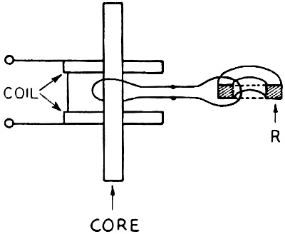
Fig. 9 - Transformer-coupled link for coupling to a ferrite torus. The simplest type of vibration that uses circular bias is the radial vibration of a ferrite torus with a toroidal driving winding on it. The flux produced by the winding alternately adds to and subtracts from the permanent bias flux, thus causing the circumference of the torus or ring to vary at the frequency of the driving current. As the circumference varies so must the radius, and the actual motion of all parts of the ring is in and out from the center. To give an idea of dimensions, a thin ferrite ring one inch in diameter would resonate in this mode at about 65 kc., and for other diameters the frequency would be equal to 65 divided by the diameter in inches. The maximum possible coefficient of coupling between a tuned circuit and a ferrite resonator is obtained when the coil is wound toroidally on a radially vibrating ring and the bias is optimum. A toroidal winding of many turns is a nuisance to put on, especially since it must not be tight on the ring, which would interfere with the vibrations. However, a few turns may suffice for some purposes. For example, oscillations can be produced in the circuit of Fig. 6 if point P is connected to ground by a single short piece of wire passing through a ferrite ring. This might be called a "one-turn toroidal winding." Of course, oscillations are obtained more easily if several turns are used. The effect of a multi turn winding may be obtained to some extent by transformer action, as shown in Fig. 9. Here a multiturn winding, consisting of two "pies" on a magnetic core, acts as one winding of the transformer while a turn or two of wire around the core acts as secondary winding and is connected to a one-or-more turn toroidal winding on the ferrite resonator ring, R. This arrangement works very much as if the many turns were wound directly on the resonator; that is, provided a good high-permeability core is used, such as a piece of high-permeability ferrite. The core, of course, does not vibrate mechanically; it acts only in the ordinary way as the core of a transformer. Crossed Fields
Fig. 10 - Crossed bias and exciting fields result in shear stresses in a ferrite rod of rectangular form, as shown by the vector diagram at the right.
Fig. 11 - Coupling to a ferrite cylinder in shear vibration.
Fig 12 - Another type of vibration in a ferrite torus. B and C show methods of coupling to the vibrator. So far it has been assumed that the driving flux alternately adds to and subtracts from the bias flux. What happens if these fluxes are at right angles to each other? One way to figure this out is to suppose we have a square piece of ferrite with a bias field across between one pair of opposite edges and a driving field at right angles, as shown in Fig. 9. The bias field may be represented by a large vertical vector and the driving field by a small horizontal one. But it is equally possible to consider the bias vector as composed of two large diagonal vectors and the driving field as the resultant of two small diagonal vectors, as shown. It is now seen that along one diagonal the fields aid and along the other diagonal they oppose. Thus, the effect of the driving field is to distort the square into a slightly diamond shape. Such a distortion is called a "shear" and the perpendicular arrangement of bias and driving fluxes can be used to drive resonators whose vibrations set up shearing stresses. Perhaps the simplest example of such a resonator is a cylinder or pipe vibrating torsionally; that is, one end rotates one way while the other end rotates in the opposite direction. The center does not turn but the greatest shearing stress or twisting force occurs there. Fig. 11 shows a ferrite tube, permanently biased as previously explained, with a driving coil located over the node of motion (shown dotted). The frequency of a torsional resonator of this sort depends only on its length, and for ferrite the frequency in kilocycles is approximately 65 divided by the length in inches. (It is just a coincidence that a magnetostrictive ferrite has approximately the same frequency for a torsional resonator of length L as for a radially vibrating ring of diameter L.) Another example of a vibration mode involving purely shearing stresses is shown in Fig. 12A. Here the outer portion of a disk rotates in one direction while the inner portion rotates oppositely. Between these rotations is a ring of no motion which is called a "nodal ring." This type of vibration might be called concentric shear because the motions are in concentric circles and the stresses are pure shear. The frequency depends on the size of the hole. If the hole is very small, the frequency for a ferrite disk is approximately, in kilocycles, 215 divided by the diameter of the disk in inches. It will be noted that it is independent of the thickness. If, on the other hand, the hole occupies most of the disk, the frequency becomes approximately 131 divided by the difference between outer and inner diameters. Fig. 12B shows how a flat coil is placed against one side of the disk to drive it in the concentric shear mode. The dotted line represents a typical line of driving flux. The bias flux lies in concentric circles within the material, thus being at right angles to the radial driving flux. A better coupling can be obtained by enclosing the driving coil in a "pot" of magnetic material, as shown in Fig. 12C, and a still further improvement should result from using another similar driving system on the other side of the disk. [The second part of this article, to appear in a subsequent issue, will discuss applications of mechanical resonators and the use of ferrites in filters. - Editor]
Posted January 2, 2020 |
|