|
Final Tuning Knob for the Heath "Sixer"
The final-amplifier tuning capacitor in the Heath Twoer and Sixer happens to
be a ceramic trimmer not normally accessible from the outside of the cabinet. In
order to dip the final, one of two methods is usually used to reach the trimmer;
either the unit is removed from the case or a screwdriver is inserted in a hole
drilled in the side of the cabinet. However, this is not always so easily done,
especially if one is working mobile. The author solved this problem by making a
built-in self-retracting knob which is always handy, but which is not in the way
during removal of the unit from the case. As shown in Fig. 1, the knob is not
fastened to the trimmer and thus will not put any strain on the capacitor or its
associated wiring.
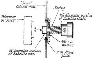
Fig. 1 - Details for assembling a final-amplifier tuning
control for a Heath Sixer or Twoer.
Begin the modification by drilling a 1/2-inch diameter hole in the case directly
in line with the trimmer adjusting slot. Make a 1-inch square plate from 16 gauge
aluminum stock and drill a 11/64-inch hole in the center of the square. Drill two
1/8-inch holes in the plate for mounting the plate to the case. These holes should
be a little bit on the sloppy side for the screws that will be inserted in them,
since the trimmer does not always return to the exact same spot each time the unit
is put back in the cabinet. I used screws from an old Command receiver to fasten
the plate to the case. Drill two holes in the cabinet to mate with the mounting
holes on the plate, being careful to make the holes small enough to allow the screws
to self-tap.
Chuck 1/4 inch of a 1 1/4-inch length of 1/4-inch diameter bakelite rod in an
electric drill. Use a file to turn down the diameter of the remaining 1-inch length
of rod to 5/32 inch. File a screwdriver bit on the face of the 1/4-inch diameter
portion, as shown in Fig. 1. Mount the plate on the case and insert the bakelite
rod through the plate. Slip a 5/32-inch i.d. washer over the shaft, along with a
small 5/8-inch long coil spring and a suitable knob, such as the antenna trimmer
knob from a Command receiver. Make sure there is enough compression on the spring
to keep the rod retracted. After all the parts are assembled and the unit is installed
in the cabinet, it is only necessary to push in the knob and rotate it until the
shaft bit engages the slot of the trimmer. - Frank M. Wing, W4TUO
Calibrating Inexpensive Signal Generators
inexpensive wide-range signal generators that use air-core coils can be calibrated
exactly, even though they don't have an individual calibration adjustment for each
band. Stuff a length of spaghetti tubing with aluminum foil and insert it into the
coil to be adjusted. Slide the tubing in and out of the coil until zero beat is
achieved on a calibrated receiver. For best mechanical stability, the tubing should
fit snugly in the coil. - Lou Fuentes, WB2MYN
(Since an aluminum core lowers the inductance of a coil, the above method of
alignment will not work on those bands where the coils employed have too little
inductance. This situation can he corrected by the following technique: Switch the
generator to the band which is in error on the high-frequency side by the greatest
percentage and fix the position of the tuning capacitor at some convenient frequency.
Unloosen the pointer and reattach it at the correct calibration mark. Proceed to
calibrate the other bands as suggested by WB2MYN. Observe, however, that the calibration
points may or may not be true across the entire scale. Also note that inserting
aluminum foil in an air-core coil will lower the Q of the inductor; in some cases,
the reduction in Q of an oscillator coil might cause the circuit to cease functioning.
- Editor.)
Cable Racks
I have found that hose racks, ordinarily used for the storage of garden
hose on the side of a house, are ideal for keeping accumulated wire and coaxial
cable in order. Aluminum racks, which sell for about 75 cents each, make excellent
spools for lightweight wires and cables. Steel models cost approximately a dollar
apiece and are useful for storing heavy cable such as RG-8/U. Garden-hose racks
are sold by most hardware stores. -Julian Lovejoy, W1BT
Equipment Feet
Football shoe cleats come in many varieties. The hard rubber and nylon types
that are threaded make good standoffs or feet for electronic equipment. Cleats are
available from most sporting-goods stores. - Karl Hatfield, W6BXR
|
Thumb-Groove Indexing the Handbook
Sections of the Handbook that are frequently used by the reader can be located
quickly by filing thumb grooves in the Handbook pages as shown in Fig. 3 and
labeling these grooves as pictured in Fig. 2. As illustrated in the second
sketch, I filed thumb grooves for only three subjects: the wire-size table, the
tube index and the general index. These items seem to fill 99 percent of my general
requirements. Other grooves can be added at any time, but usually the sections of
the book they indicate are only of short-term use. - Norm Cucuel, K1LFH
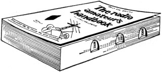
Fig. 2 - K1LFH's method of thumb-groove indexing the Handbook.
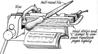
Fig. 3 - One method of labeling the thumb grooves.
Adhesive-Backed Terminal Board Eliminates Mounting Screws
The low-profile terminal board shown in Fig. 4 is especially useful in dense
electronic circuits where mounting space and working space are limited, and where
it may be undesirable or impractical to use mounting screws or other hardware fasteners.
The terminal board consist of 0.012-inch-thick copper terminal strips cemented between
0.032-inch-thick fiberglass sheets which have a thin layer of pressure-sensitive
adhesive backing. Scoring between terminal pairs facilitates detachment of the required
number of terminals for specific applications. For soldering connections, the copper
terminals are bent outward. The boards are mounted by pressing the adhesive backing
onto a mounting surface in the equipment package. - NASA Tech Brief 65-10396
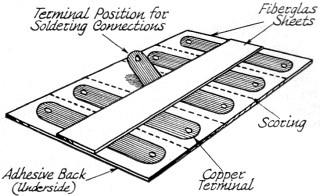
Fig. 4 - Details of the adhesive backed terminal board.
Grommet Cable Holder
One way I have found to make a chassis wiring job neater is to use rubber grommets
as wire bundle holders as shown in Fig. 5. If the approximate number of wires
that will pass through each bundling point can be predetermined, it will be easy
to pick out the proper size grommets to secure a tight fit.
Phil MacDonald, WA1CTQ

Fig. 5 - The rubber grommets, shown here as cable holders,
should be chosen to firmly secure the wires in neat bundles.
Phone-Jack Panel Bearing
As shown in Fig. 6, a panel bearing can be made from all extra phone jack
by filing away the flange on the inside of the jack and removing the excess contacts,
soldering lugs and phenolic insulation. The bearing will be suitable for a 1/4-inch
shaft if a standard phone jack is used for the modification. -John Wallace, WA5NPE
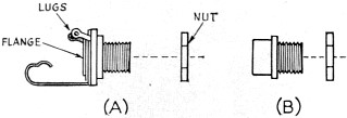
Fig. 6 - By filing away the flange and removing the excess
parts, a phone jack (A) becomes a panel bearing (B).
|

 Table
of Contents
Table
of Contents