Hetrofil - An Aid to Selectivity |
|
This "Hetrofil," (sometimes errantly referred to as a "Heterofil") shorthand for "heterodyne filter," was conceived of, designed, and built by author Raymond Woodard. A Wien bridge is used to selectively null out interference caused by leakage of the heterodyne beat frequency into the audio (phone) circuit. The beauty of the Hetrofil is only a few inexpensive passive components are needed. It is inserted between the receiver headset jack and the headset. A couple years later, Wade Caywood applied the Hetrofil concept to an oscillator tuning and stabilization circuit (see "An Amateur Application of the Wien Bridge," January 1941 QST. Also, a form of the Hetrofil was used in Hewlett-Packard's Model 200A audio generator. Hetrofil-An Aid to Selectivity An Audio "Phasing Out" System for Eliminating Heterodyne Interference By Raymond W. Woodward, W1EAO
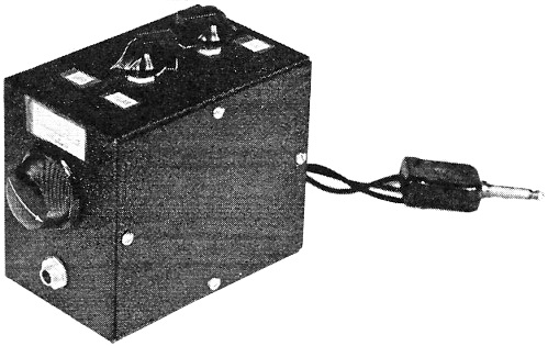
The Hetrofil fits into a 3 X 4 X 5-inch box with room to spare. The plug goes into the 'phone jack on the receiver; the 'phone plug into the jack on the case. In these days of complicated thises and thats, it's rare indeed to find something exceedingly simple and yet exceedingly effective. Hetrofil is a gadget which can profitably be added to any receiver, from the simplest one-lunger up to the most elaborate multi-tuber, calls for no tube or power supply, no digging into the receiver's innards, and can be built from a few inexpensive parts. It does a really remarkable job of wiping out an interfering heterodyne, a point on which you can convince yourself by giving the circuit a try. You won't be able to avoid waxing enthusiastic. The crystal filter has been a boon to users of communication receivers as an aid in separating two signals, rejecting an unwanted one and accepting a desired one. However, its use is restricted to superheterodyne receivers and generally to the more expensive models as well. Thousands of users of t.r.f. receivers and lower-priced superhets are denied its advantages and, it might be added, many operators having crystal filters fail to use them because they have not mastered the proper operation. The purpose of this article is to describe a device which can be applied to any receiver and affords a means of rejection similar to the "phasing" action of the crystal filter. It is simple to operate, requires no tubes, and best of all, costs less than a good crystal. Simply plug it into the 'phone jack of the receiver, the 'phones into a new jack on the box and there you have it. By rotating a knob an interfering c.w. signal or a 'phone heterodyne can be eliminated. The basis of the device is the Wien bridge, which is an alternating current bridge ordinarily used to measure audio frequencies. For instance, such a bridge might be used in precision measurement of radio-frequency signals as a means of measuring the audio residual or beat note obtained between a 5- or 10-kc. multivibrator and a signal being measured, and in this manner amateur frequencies can readily be measured with an overall accuracy of ± 50 cycles.
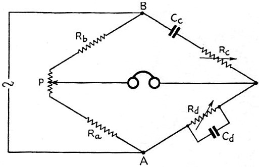
Fig. 1 - Fundamental Wien bridge circuit. It was while using the Wien bridge in frequency measurements that the writer considered the circuit could be applied to receiver outputs and the sharp balance or null point used to remove a troublesome heterodyne. Trial showed the theory was sound so a simplified version of the Wien bridge - "Hetrofil" - was constructed and given operating tests. By its use many a QSO has been carried out that would have been impossible without it (or a crystal filter) on both 'phone and c.w. Now, every ham who comes into the shack wants to know what is in the little box. So here it is. Fig. 1 shows the basic Wien bridge as used in audio measurements. In this bridge the unknown frequency is applied across A and B (generally through an isolating transformer) and the resistance Rc and Rd varied until a null or absence of sound is indicated in the 'phones or other detector.
Fig. 2 - The "Hetrofil" circuit.
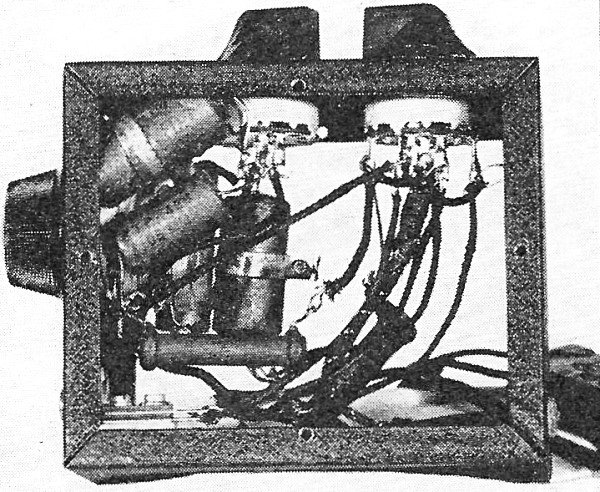
The "Hetrofil" chassis. Then the unknown frequency
provided also
Now if Cc is made equal to Cd and Rc equal to Rd as well as the ratio Rb/Ra = 2, then the expression for frequency reduces to
These conditions are easily met, and Rc and Rd can be two identical variable resistors mounted on a common shaft. P is a small variable for aid in establishing final balance. For measurement work accurate components are necessary, but for the purpose at hand the bridge can be simplified and ordinary parts of commercial tolerances used, although the more accurate they are the more effective the device. In addition, means should be provided for switching the device in or out of circuit as well as to change the frequency range. The fixed resistors and condensers may be of small size as no power or high voltage is involved. The dual variable resistors should preferably have a logarithmic taper and be of like values. Those at present available in the amateur supply houses do not exactly meet these requirements, but it is hoped that more suitable items will shortly be available for this purpose. The values shown for R1 and R2 have been found satisfactory when working into a receiver 'phone output intended for regular 2000-ohm 'phones. If the device is inserted in a 500-ohm circuit or the low-impedance line to a voice coil the resistors will have to be altered to suit the lower impedance. Proper values can be found by trial, keeping in mind that the ratio of R1 to R2 should always be 2 to 1. Naturally, inserting any resistive network in the audio output will attenuate the signal somewhat. However, this is no great disadvantage as practically all receivers have an excess of audio available and the audio gain can be advanced to offset the loss. Using commercial parts, the model shown has an average loss of 10 to 15 db. With more accurate units and with a more perfect impedance match with the receiver the loss can be reduced to the order of 5 db. There is also some frequency discrimination so that some frequencies are attenuated more than others, as will be shown later. This results in some distortion of 'phone signals, but this also can be tolerated, when it is a case of receiving the signal or not, and is no more a detriment than the use of a crystal filter on 'phone signals. Fig. 2 gives the Hetrofil circuit as used for communication purposes, and the photographs show the arrangement of parts in a small box 5 by 4 by 3 inches. A cord out the rear has a plug for connecting to the receiver, while a jack on the front takes the regular 'phone plug. The two knobs on the top control switches S1 and S2 and the knob on the front provides the variable control to adjust to the frequency to be eliminated. In use the device normally has the switch S1 in the "off" position connecting the 'phones straight to the receiver. When an interfering c.w. signal or 'phone heterodyne appears, switch S1 is thrown to the "on" position and the audio gain advanced if necessary. The dual variable-resistor control is then rotated until a position is located where the interfering heterodyne disappears. The point of complete elimination is quite sharp and effective. The Hetrofil, of course, completely eliminates only one frequency. If there is harmonic distortion in the beat note being eliminated, as may be the case with exceptionally high audio output or faulty audio circuits, the higher harmonic" will remain after the fundamental is removed, Generally, these are too weak to be noticed. The selection of condenser C1 or C2 by switch S2 is dictated by the particular frequency to be rejected. Calculation using the formulas given above shows that C1 will have a lower limit of about 320 cycles (when all resistance is in circuit) while C3 will go down to about 65 cycles. Thus, if the beat note is less than about 350 cycles C2 has to be used. For all higher frequencies C1 should be used as it gives much sharper rejection and less attenuation.
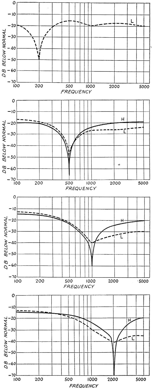
Fig. 3 - Attenuation over the band 100-5000 cycles for four representative settings of the rejection frequency. A great many transmission curves have been obtained using different values of fixed resistors and condensers with the circuit set to reject various frequencies, from the lowest to the highest, and the attenuation throughout the audible range studied. To do this a constant-level source of audio voltage from a beat frequency oscillator was applied to the input of the Hetrofil and the output measured with a General Radio Sound Analyzer. The use of the latter equipment to measure the output eliminated the effect of any residual audio harmonics which might be present at the null point or at any other of the frequencies measured. Looking inside, with the side covers removed. The dual volume-control type variable resistor, at the left on the front wall, is partially concealed by the fixed condensers. Fig. 3 shows curves typical of those obtained. In this case the constants of the Hetrofil circuit shown in Fig. 2 were used and the controls set to eliminate 200-, 500-, 1000- and 2000-cycle signals. The solid lines show the results with S2 set on the high side or with 0.05-μfd. C1 condensers in the circuit, while the dotted line is for the low setting of S2 with the 0.25-μfd. C2 condensers. These curves were taken with commercial-tolerance resistors and condensers, and it should be pointed out again, do not represent the maximum results possible with more accurate components. With the high setting the peak rejection is about 70 db and at 10 per cent off resonance about 40 db. It then tapers off to about 13 db at the low frequencies and 20 db at the high frequencies. With the low setting the peak at the higher frequencies is not so pronounced and the high frequency attenuation somewhat greater. As previously mentioned, this causes some distortion of 'phone signals and accounts for the preference for the use of the high setting where it is permissible. When the low setting (C2) is used to reject a low frequency beat, say 200 cycles, the transmission curve is, as shown, practically flat as regards frequency distortion. In using the Hetrofil on c.w. reception the frequency distortion is of no consequence and is only apparent as a "turning over" of the background noise level as the control is varied. Naturally, many other uses of the Hetrofil circuit will suggest themselves. It is perfectly feasible to use the circuit with a receiver already equipped with a crystal filter and thus afford a means of eliminating more than one interfering heterodyne. Indeed, if the receiver has enough audio gain two or more Hetrofils can be used in series to reject two more beat notes. One might even construct a deluxe model with a stage of audio ahead of two Hetrofil circuits and the switching so arranged that as each Hetrofil is cut in the audio gain would be automatically advanced to keep a constant level. But then the extreme simplicity of the device, its major advantage, would be lost. If applied to superregenerative receivers the audible interruption frequency can be taken out quite well where a separate tube is used as an interruption frequency oscillator and fairly pure tone is generated. Where a self-quenched detector is used and a hiss of considerable bandwidth is obtained, the Hetrofil will remove the major part of the hiss but not all.
Posted October 19, 2022 |
|