Flexible Coaxial Cable |
|
If anything qualifies for meeting the criteria of the old adage that says "Necessity is the mother of invention," it is coaxial transmission cable. Wireless communications during World War II was the necessity that drove the rapid development and continuous improvement of coax. Other than materials technology for wire, dielectric, protective jacket, etc., the basics of coax cable have not changed since this article appeared in a 1946 issue of QST magazine. It was during the war that polyethylene was developed and adopted as a dielectric material much superior to previously used copolene. Understanding of how electromagnetic fields propagate within and, under non-ideal conditions - on the outside of the cable has increased significantly thanks for refined theory and high speed computer simulations. RG-58 were early 50 Ω coax types, and RG-59, RG-11, and RG-6 were early 75 Ω coax types that are all still in significant use today. Flexible Coaxial Cable Many a ham was impressed during the war with the wonderful advances that were made in flexible coaxial cable, and many a ham now has an eye on some for his new or revamped rig. Here is a story for the fellows who didn't have a chance to become acquainted with it during the past few years.
a = outside radius of inner conductor
(inches) ε = dielectric constant = ε0
* εr New Developments in Solid-Dielectric Lines By Ringland M. Krueger * Many electrical components were improved considerably during the accelerated development and production programs of the war, and modern semi-flexible solid-dielectric coaxial cable is an outstanding example. Expedited by the close joint cooperation of the various manufacturers and the armed forces, under the leadership of the Army-Navy R.F. Cable Coordinating Committee, a number of types were developed and produced in large quantities, to the close mechanical and electrical tolerances necessary for full interchangeability of sections of like type designation. These cables had to withstand the extreme cold encountered at high altitudes, the terrific heat in mobile equipment stationed on a desert or on a South Pacific island, the bending experienced in the turret of a tank or the scanning radar antenna in a bomber, and the terrific shock when mounted on a battleship firing a full salvo. The first flexible coaxial cable was made with bead spacers, but there was always the definite danger of moisture collecting within the cable and seriously reducing the breakdown voltage. For example, when a fighter plane or bomber climbs rapidly from near sea level to a high altitude, the temperature of the plane may drop as much as 100 degrees F. in a matter of minutes, and this sudden reduction in temperature causes condensation of any water vapor present in the air within the cable. It was, therefore, imperative that a solid-dielectric coaxial cable be developed, to eliminate all air spaces between the center conductor and shield. The first solid-dielectric semi-flexible cable, meeting the electrical and mechanical requirements of the Services prior to Pearl Harbor, used a dielectric called "copolene." Early in the war, through the joint cooperation already mentioned, "polyethylene" was developed and adopted as the dielectric material. Polyethylene has a host of desirable characteristics as a dielectric for solid coaxial cables. It is very flexible under extreme cold and readily passes a cold bending test at temperatures as low as -40 degrees C. It has a high softening point and will withstand temperatures as high as 185 degrees F. Of paramount importance, however, is its excellent low power factor of 0.0003 to 0.00045 and its dielectric constant of 2.29, the combination of which produces a desirable low loss factor. Polyethylene is not affected by acids, alkalis, aviation gasoline, oil, hydraulic brake fluid or sea water. There is no known solvent for polyethylene at ordinary temperatures. From an electrical standpoint, polyethylene is almost comparable to polystyrene and it has the advantage of flexibility. Solid polyethylene coaxial line has more constant impedance than washer-spaced lines, because the dielectric material is homoge-neous and of constant diameter over the entire length of the cable. The center conductor of solid coaxial cable is made of either solid or stranded copper wire, and in some lossy applications a nichrome-wire inner conductor is used. A polyethylene sheath is extruded over the inner conductor, and several inspections are made to insure constant diameter and permissible eccentricity. The eccentricity is tested by X-ray methods and is held below 10 per cent. For the smaller cables, this is only 0.0055 inches! The outer conductor is then woven over the core. This conductor is usually one or two layers of bare copper braid, but for some special applications the braid is made of tinned-copper or of a silver-coated braid covered with a plain copper braid. The braid in turn is covered with a vinylite jacket. Vinylite - or "vinyl" - is a plastic material that is unaffected by oils, gasoline, hydraulic brake fluid, water or sunlight, and its weatherproof qualities have proved themselves many times in the past few years. Some cables for military applications are made with an additional steel-braid armor jacket over the vinyl, but these are of limited interest to amateurs. One great advantage of solid coaxial cables like those described above is that they are very easy to install, and can even be buried in the ground without additional treatment. Extended tests on cables buried underground for fifteen months, in a naturally low spot where water or frost was a constant threat, showed no ill effects on the cable either mechanically or electrically. Actually, no change in the electrical characteristics could be detected with very precise measuring equipment.
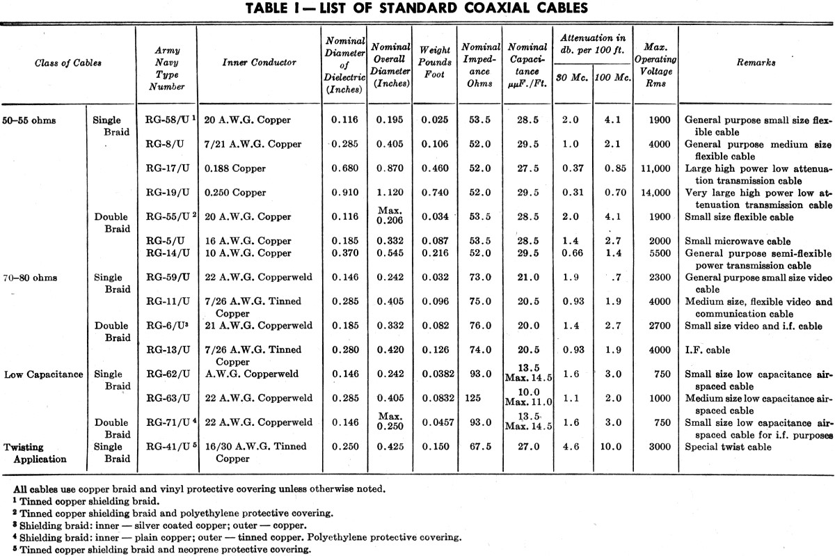
Table 1- List of Standard Coaxial Cables Velocity factor is s term used to describe the decrease in velocity of transmission in a coaxial cable and is expressed as a percentage of the velocity in free air. In other words, if r.f. energy has a wavelength of 100 cm. in air and only 66 cm. in coaxial cable, the velocity factor is 0.66. A method of determining this factor is to select a piece of cable and connect a small half loop between the inner and outer conductors at one end of the cable, leaving the other end of the cable open. The half loop is then coupled to a grid-dip meter and the lowest frequency is found that will dip the meter. The cable is an electrical quarter wavelength at this frequency, and the velocity factor can be computed from
where F = velocity factor f = frequency in Mc. L = length in feet If the far end is short-circuited, the length becomes a half wave and the above formula requires a constant of 492 instead of 246. The coupling loop must be made as small as possible consistent with sufficient coupling to the grid-dip meter, or else a small error will be introduced. Incidentally, this grid-dip meter method is an excellent one for checking the electrical length of a quarter-wave piece of coaxial line used as a matching transformer between the radiator in a close-spaced array and a higher-impedance transmission line. Coaxial cables suitable for feeding antennas are available in impedances of 50 and 70 ohms. Wide variations in physical size and power capabilities are available, as can be seen from Table I, a compilation of the standard cables now available and most likely to be used by amateurs. The proper selection of cable types depends upon the requirements, such as the operating frequency, desired impedance, power level and the length of the cable run (attenuation). A low-capacity line is available. It has a novel type of construction that uses a small thread of polyethylene spiraled around the center conductor to act as a supporting medium in a tube of polyethylene. The conventional shield braid is placed over this, along with the normal jacket. This particular type of line is used where low capacity and not constant impedance is the important factor. "Twin Lead" Parallel Line A new development of great interest to the amateurs who have tested it is Amphenol's polyethylene insulated "twin-lead" line, which is manufactured in impedance values of 300, 150 and 75 ohms. The 300-ohm line was brought out under recommendations of the R.M.A. as a standard impedance for use with television and facsimile receivers. Amateurs, always quick to adopt new ideas, have utilized "twin-lead" for feeder applications in the bands now open. This line was not brought out with the thought in mind of supplying the amateurs with a transmission line, but reports have been received indicating successful performance of the 300-ohm line with 500 watts of power at 30 Mc., where the standing wave ratio was less than 2 to 1. The attenuation of the 300-ohm line is 0.88 db. per 100 feet at 30 Mc., and its velocity factor is 0.82. This line is excellent in dry weather, but being an open type of line some change in impedance is to be expected when frost, condensation, or rain collects on the line, or when it is run closer than several inches to metallic objects. It is therefore recommended that, for the best all-around operation in any type of weather, a coaxial line be used in place of any parallel-wire type of line. However, many amateurs may feel that the lower-priced "twin-lead" line will be satisfactory for his operations, and this is quite true provided he is familiar with its limitations. Coaxial cables have been used very extensively throughout the entire war period and have been most satisfactory under all possible conditions. It is felt that the amateur will use more coaxial cable for links between the various stages of his transmitter and for his antenna feed. He will find that he has not only an excellent antenna set-up, but that regardless of weather conditions he will not be bothered by flash-over of his feed line while "on the air." * American Phenolic Company, Chicago, Ill. 1 - Mix, "A Low-Power 28-Mc. 'Phone - C.W. Transmitter," QST, March, 1946.
Posted September 6, 2022 |
|