Coupling to Flat Lines |
|
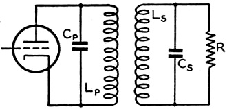
An ample supply of surplus coaxial cable after the end of World War II provided an inexpensive and easy to use form of transmission line. Not having to worry about cable routing and unintentional radiation makes transitions through walls, running along metal surfaces, and routing high power transmission lines near habitable areas a no-brainer. Issues like power handling, bend radius, and higher attenuation need more attention during the installation design phase, but that pales in comparison to coaxial cable's advantages. In this 1947 issue of the ARRL's QST magazine, author Byron Goodman addresses some of the issues Hams accustomed to using flat transmission lines (conductor pairs separated by an insulator). Coupling to Flat Lines - Circuit Considerations for Matched-Line Coupling Fig. 1 - A load R is coupled to a tube through circuits LpCp and LsCs. R can be connected in parallel as shown, or in series. By Byron Goodman,* W1DX Here is a story full of useful information for the operator who has been having trouble coupling to a "flat" line. It explains why some lines to require very tight coupling and why some don't, and it tells how to insure that you will have no coupling difficulties. The widespread use of 50- and 75-ohm coaxial lines for feeding amateur-band antennas has introduced the amateur to some problems that he was unprepared for through his experience with higher-impedance tuned lines. The following discussion will cover only the coupling of transmitters to a pure resistive load, such as is presented by a properly-matched coaxial or parallel-wire transmission line. It must be remembered that whether or not the line is matched - and hence presents a resistive load at the transmitter end - is dependent entirely upon the load at the antenna end, and no amount of adjustment at the transmitter end will correct for an unmatched condition. The condition of match at the antenna end results in no standing waves on the line, and the line is called a "flat" or untuned line. It is perfectly possible to put power into a line that isn't "flat," as is done with any tuned line, but there seem to be some misconceptions about coupling into untuned lines. In the past, many amateurs have acquired a "flat" line and then blithely connected the transmitter end of the line to a few turns jammed into the transmitter tank coil. Sometimes it "loaded" and more often it didn't. The poor results were usually blamed on the flat line, but so were the good results, and it may be difficult to reconcile the different results. A little discussion of coupled circuits may clear up some of the questions.
Fig. 2 - A parallel circuit, A, and a series circuit, B. The series and parallel notations are derived from the connection of the resistance. Normally we couple two resonant circuits, as in Fig. 1, at the value of coupling called "optimum," which is the amount of coupling obtained just before the tuning starts to broaden out and interlock. The coupling is a factor depending on the mechanical relation of the coils in the two circuits under consideration, and approaches a maximum value of 1. In practice, however, a value of 0.1 is readily obtainable and anything above about 0.3 becomes difficult with adjacent coils. With overwound or interwound coils, values up to 0.7 can be obtained. The value of optimum coupling is given by the relation
where Qp and Qs are the primary- and secondary- circuit Qs, respectively. Since we normally design our plate tank circuits with a Q of about 12 (see ARRL Handbook), Equation 1 above shows that, for ko = 0.1 (a practical value, remember) an antenna-circuit Q of over 8 is required. If the antenna-circuit Q becomes too low, it will require a higher value of k to reach ko, and this may be a physical impossibility. This is the condition generally described as "it won't load up!" The Q of the parallel-tuned circuit in Fig. 2-A at resonance is given by Q = 2πfCR where R is the resistance in parallel with the tuned circuit. When the resistance R is in series with the tuned circuit, as in Fig. 2-B, the equation becomes
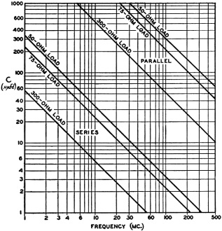
If a value of Q = 10 is assumed, and values of C calculated from Equations 2 and 3 for various frequencies and values of resistances, a family of curves is obtained as in Fig. 3. Inspection of these curves will show the best way to couple one's flat line to the transmitter. Suppose, for example, one is using a 75-ohm line to feed a beam on 29 Mc., and the line is flat. The 75-ohm lines in Fig. 3 intersect the 29-Mc. line at 740 μμfd. for parallel tuning and at 7.4 μμfd. for series tuning. Thus if one is to couple his 75-ohm line to the final tank he can connect the line as in Fig. 2-A (the resistance R represents the line) and use a capacity of 740 μμfd. and the small coil necessary to resonate at 29 Mc. (a very small coil, in this case!), or he can use the series circuit of Fig. 2-B and a capacity of 7.4 μμfd., with the correspondingly larger coil required to resonate to 29 Mc. with 7.4 μμfd.
Fig. 3 - The capacity necessary for a tank Q of 10 with 50-, 75- or 300-ohm loads, connected in series or in parallel. The curves of Fig. 3 are for an antenna-tank Q of 10, which is the correct value for a plate tank-circuit Q of 12 and a coupling factor of 0.09. Tighter coupling will allow the antenna-circuit Q to be reduced, and less C will be required for the parallel circuit and more for the series circuit. An antenna - it should be "line" - that "won't load" is the result of not having adequate Q in the antenna coupling circuit, and the curves of Fig. 3 can be used as a starting point for determining the proper circuit and the approximate L-to-C ratio when coupling to flat lines. To use the graph, find the intersection of the resistance-load line with the operating frequency for both series and parallel tuning. This will give two values of capacity. Select the more reasonable value of capacity of the two, and build a coil that will resonate with this capacity to the operating frequency. Then connect them to the line and you will have no trouble "loading" the transmitter. If the condenser for series tuning is selected, then the antenna line must be connected in series, of course. A glance at Fig. 3 will also show that if you are using, for example, a "flat" 75-ohm coaxial line on 144 Mc. but the system loads nicely when you put a 20-μμfd. tuning condenser across the antenna coil, you don't have a flat line! If the line were flat, about 150 μμfd. would be required for parallel tuning, and your results would indicate that your line is presenting a much higher load than 75 ohms to the antenna coupling circuit or that the coupling factor is high. The chart also shows that at 50 Mc. a 300-ohm line requires about 1.0 μμfd. for series tuning or 100 μμfd. for parallel tuning. Since the normal reaction is not to use a coil large enough to resonate to 50 Mc. with 1 μμfd. for series tuning, or to use as much as 100 μμfd. for parallel tuning, it is easy to see why 300-ohm lines "won't take the soup" at 50 Mc., and one usually ends up by jamming a large coupling coil in the final amplifier tank when this type of line is used. A small copper-tubing coil of 1 or 2 turns and a larger condenser for parallel tuning would make the line "load" as it should. It is hoped that, with the aid of the chart, more amateurs will realize that series tuning, with the proper L-to-C ratio, is generally necessary for coupling to low-impedance lines. When using a series-tuned circuit with coaxial line, it is advisable to connect the rotor of the condenser to the outer conductor of the coaxial line. This junction can then be grounded, if any hand-capacity effects are observed. * Assistant Technical Editor, QST.
Posted June 16, 2022 |
|


