Automatic Antenna Switching |
|
In this article from a vintage issue of QST magazine, the author describes the automatic antenna switching system which was developed for controlling the forty-odd receiving antennas at the FCC's Grand Island Monitoring Station (Nebraska). With this system it required only a matter of seconds for the operator to select any desired antenna by simply pushing a couple of buttons on the control panel. A similar system could easily be designed for a lesser number of antennas either for a test range or an amateur radio operation. Of course modern-day antenna switching equipment does the job handily and at a good price. Automatic Antenna Switching A Simplified System for Instantaneous Selection from a Number of Units By Alfred K. Robinson EX-W7DX
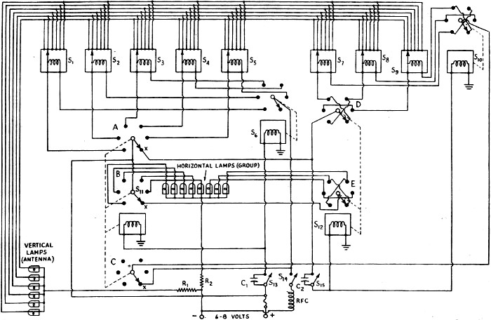
Fig. 1 - Antenna-feeder switching system. Only one feeder wire is shown in each case; connections for the second wire are duplications of those shown, and are made through a second section of each of the three-gang switches. (Connections to the third switch section are shown in Fig. 2.) R is a 200-ohm resistor.
Fig. 2 - D.C. circuit of the third switch section. The negative terminal of the battery is grounded at the chassis.
The Field Division monitoring stations of the Federal Communications Commission must be able to determine quickly and accurately the operating frequencies of all classes of radio stations, including those of the Army, Navy, and other government agencies. They must be able to make bandwidth and modulation measurements and many other technical studies, such as channel-occupancy surveys, wave-form analyses, keying checks, emission tests, and a great number of other tasks of a highly specialized nature. To accomplish these duties requires apparatus capable of the greatest possible degree of accuracy. Since standard equipment is not always available, the Commission's field inspectors often must design and construct special apparatus which may be required for a particular application. This has been true in the case of the antenna systems required. The Commission's monitoring stations require a wide variety of antennas. For instance, as many as seven medium and low-frequency double-ended Beverages, nine double-ended high-frequency rhombics, four multiple doublets, several simple doublets, beams, verticals, and long-wire antennas are used at a single location. Antenna Requirements The necessity for such extensive antenna systems is not hard to understand when one considers the large number of stations on the air with their multiple-frequency assignments and duplicated channels. An example of how valuable these antennas become is apparent from the fact that with a single Beverage, elimination of practically all except those stations located on a line with the antenna is possible. Also there is the probability of being able to select as desired either of two stations on such a line if one is in one direction and the other in the opposite direction, even though one of these stations is several hundred miles farther away. C1, C2 - 0.5 μfd. RFC - 80 turns No. 16 wire on a 2.inch diameter form. A, B and C are sections of S11, while D and E are sections of S12 (see Fig. 1). R1, R2 -15 ohms. Administration, which has made use of such engineering, has eliminated the necessity for several times as many monitoring stations as are now in use to monitor the bands properly. Since measurements and observations vary over wide frequency ranges and because antennas designed for low-frequency operation are seldom suitable for high frequencies, there is a need for some type of switching arrangement whereby any antenna may be made instantly available if full use is to be made of the receiving facilities. Transmission-Line Switching Such a switching system, essentially automatic, is shown schematically in Figs. 1 and 2. These drawings show antenna-feeder and direct-current control circuits respectively. Notably there are no "dead-end" feeder lines connected to the receiver at any time. The system takes care of a total of forty-six antennas with the possibility of adding two more immediately. By making slight modifications the system could be extended to include eighteen more if necessary. As indicated in Fig. 1, the antennas are classified and divided into eight groups with six of one class to each group. This is done for several reasons: the inspector can more quickly select the antenna group most likely to produce without having to set up each separate antenna; switching is accomplished without "dead-end" feeder lines; better isolation between each individual feeder line and still greater isolation between groups of antennas is provided; the use of comparatively small automatic switches becomes practical and these can be mounted at the best possible point in relation to antenna termination, with a corresponding decrease in antenna feeder-line interaction. Another highly desirable reason for the grouping method of switching is to permit the best antenna of any particular class to be compared with the best antenna of other classes without switching through several other antennas. In order to keep the efficiency of the antennas at a maximum, open-wire feeder lines are used throughout. A short distance from where the transmission lines connect to the switches, the wire spacing is reduced to 3/16 inch. Such a line is practical when using dual-hole Lucite beads commercially manufactured for two-wire coaxial cables, and these make a very neat installation. The impedance is maintained approximately by the use of smaller-diameter wire. The advantage of close spacing is obvious, since the possibility of interaction because of the feeder-line connec-tions at the switches is reduced to a minimum. In this article the author describes the switching system which has been developed for controlling the forty-odd receiving antennas at the FCC's Grand Island (Neb.) Monitoring Station. With this system it requires only a matter of seconds for the operator to select any desired antenna by simply pushing a couple of buttons on the control panel. R.F. Circuit Details Each of the numbered switches in Fig. 1 consists of three sections ganged together on the same shaft. Each section has six positions and is operated by a 6- to 8-volt d.c. "stepping" solenoid which continues to rotate the switch arm, contact by contact, so long as the solenoid circuit is held closed. Fig. 1 shows only the first section of each switch. It is seen that these switches control the selection of one of the two transmission-line wires to the various antennas. The second switch sections (not shown) control connections to the other transmission-line wire in exactly the same manner. Connections to the third sections are shown in Fig. 2. These third sections of each switch control connections to the vertical and horizontal lamps on the control panel which indicate which antenna of the forty-odd available is in use at any given time. Returning to Fig. 1, it will be seen that the various antennas are arranged in groups. Anyone of six Beverage antennas may be selected by S1 and S2. Since a Beverage antenna is directional, its direction depending upon to which end of the antenna the receiver is connected, provision is made to switch the receiver to either end. S1 controls connections to the "forward" end or" each antenna, while S2 controls the connections to the "rear" ends. Connections to anyone of four multiple doublets are made through S3 and blank contacts are available for the addition of two more antennas to this group. In the next group, controlled by S4, are four h.f. beam antennas, a vertical antenna and a 250-foot general-purpose antenna. Similarly, S5 controls a group of six half-wave doublets. Connections to either end of anyone of nine rhombic antennas are controlled by S7, S8, S9 and S10. The switching of this group will be discussed later.
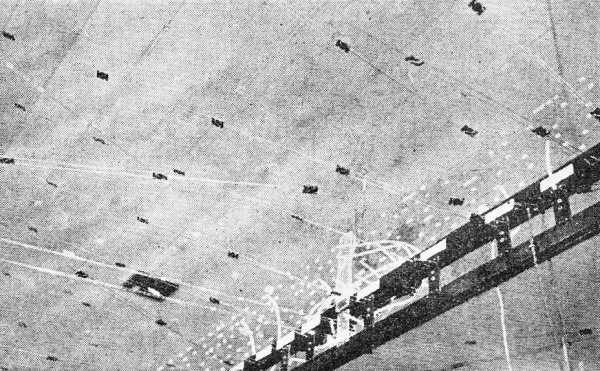
Transmission-line anchors, showing the jack connectors used for "patching" circuits when required.
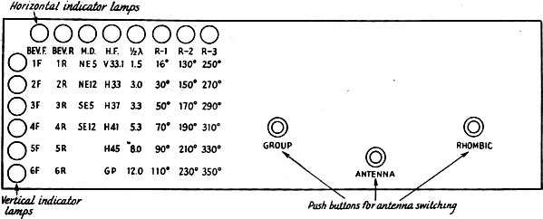
Fig. 3 - Arrangement of the control and indicator panel used with the antenna-switching system. Connections to any desired group of antennas are set up by the "group" switch, S6. Thus, to connect the receiver to any desired antenna, the "group" switch is first turned to the desired group and then the "antenna" switch for that group is turned to the desired antenna. Since more than six connections are required for the rhombic antennas and since these antennas are used to a considerable extent on high frequencies to determine the "sense" of a signal (direction from which a signal is arriving at a bi-directional antenna), this group is provided with a separate "group" switch, S10, which connects to X on the first group switch, S6 This permits around-the-compass rhombic directivity without the necessity for going through other groups while doing so. S10 selects anyone of the three rhombic antenna switches, S7, S8, S9, while the latter each provide for six different connections to the rhombic antennas. Here also connections may be made to either end of each antenna. Control Panel The control and indicator panel is shown in Fig. 3. It is only 5 1/4 inches high and of standard rack length (19 inches). Antenna designations are marked on the panel in tabulated form with an indicator lamp opposite each row of "antenna" designations and one above each column of "group" designations. This system simplifies considerably the wiring, besides saving on those parts which are so scarce and difficult to secure these days. The simultaneous lighting of one lamp in the vertical row and one in the horizontal row serves to indicate which antenna is in use. Thus, to select any particular antenna, the "group" push-button switch, S13 (Fig. 2), is held closed until the horizontal lamp lights indicating the proper group. The "antenna" push-button switch, S14, is held closed until the vertical lamp lights which indicates the desired antenna in that group. Thus, when the fifth horizontal lamp from the left and the third vertical lamp from the top are lighted, the 3.3-Mc. doublet is in use. When any of the rhombic antennas is to be used, the "group" push-button switch, S13, is held closed until one of the last three lamps in the horizontal row lights, indicating that the "rhombic group" switch is connected in the circuit. Then the "rhombic" push-button switch, S15, is held closed until the indicator lamp shows the desired rhombic group, after which closing the "antenna" push-button switch, S14, will select the desired antenna in that group. Control and Indicator Circuits Referring to Fig. 2, two operating circuits are required, one for the solenoids which operate the rotary switches and a second which furnishes voltage to light the indicator lamps. The numbered switches in Fig. 2 are ganged with the correspondingly numbered switches of Fig. 1. To begin with, it should be noted that when the "group" switch, S13, is closed the solenoids of S6 and also of an additional three-gang switch, S11 are energized, so that these two switches turn in unison as though they were ganged on the same shaft. Lamp voltage is fed to arms A and B of S11. Arm A, through its contacts, delivers this voltage to the arms of the first five antenna-indicator switches operated by S14 via S6, and thence through the contacts of these switches to the vertical row of indicator lamps. Arm B, on the other hand distributes voltage to the first five lamps in the horizontal "group" row. When section A of S11 is in the position marked X, it delivers lamp voltage to one arm of an additional switch, S12, which operates in unison with the "rhombic" switch, S10, and thence through the contacts of S12 to the arms of the last three antenna-indicator switches, S7, S8 and S9. The contacts of these switches are connected to the vertical row of lamps as shown in Fig. 2. Voltage from X also is fed through the "rhombic" push-button switch, S15, which energizes the solenoids of S10 and S12 simultaneously. When arm B of S11 is in the position marked X, voltage is fed to the arm of section E of S12 and thence to the last three lamps in the horizontal row.
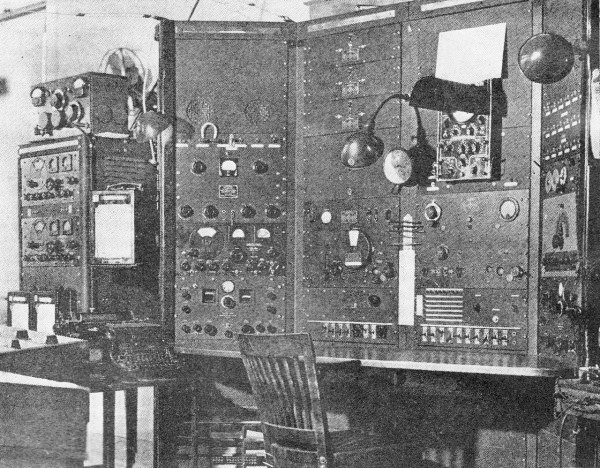
One of the monitoring bays at the FCC station at Grand Island, Nebraska. The antenna-switching panel is in the right-central rack, just above the row of Key-type switches at the bottom. When the arm of section C of S11 is in the X position, voltage is fed through the "antenna" push-button switch, S14, to the arm of S10 and thence to the solenoids of S7, S8 and S9. Components Study of the diagrams will show that very few parts are used, considering the job that is accomplished. Twelve three-gang switches, three push-button switches, fourteen lamps and sockets, a source of d.c. power, a few feet of close-spaced transmission line and other wire are all that is necessary for a workable system. The switches are of the three-section, six-position, low-loss wafer type fitted with a "stepping" solenoid, as mentioned previously. They are particularly well suited to this use, since two of the sections to the rear of each unit are well removed from the solenoid winding and have practically no other metal in the immediate vicinity. A few refinements have been added, such as condensers C1 and C2 and the r.f. choke, RFC, to prevent any possibility of clicks in the receivers from the "make" and "break" of the push-button switches. Resistors, R1 and R2 in Fig. 2 are connected in series with the lamps to prolong their life. The several units are provided with octal plugs and sockets so that they may be removed readily for service or rearrangement. To expand further the usefulness of the available antennas and to provide an auxiliary for the automatic switching system, all antenna-feeder lines are brought in to General Radio jacks, thus making it practical to "patch" to any antenna manually. The transmission lines brought to these terminal jacks are well spaced to avoid coupling. The jacks make excellent points to connect the close-spaced lines from the switching relays. The rhombic antennas shown in the diagrams belong to the Radio Intelligence Division of the FCC, which has been doing such excellent work in keeping radio channels clear of unauthorized transmissions and locating sources of interference to important wartime communication circuits. Since the rhombics are used by the RID independently of the Field Division of the Commission, the connections to these antennas must be made in a manner such as not to disturb in the slightest their use by this agency. To accomplish this a 250-ohm carbon resistor is inserted in each leg of the transmission line coming from the rhombic-group relay. Extensive tests on several frequencies have shown no interference to the RID and no perceptible loss of signal for monitoring purposes. While the usefulness of an automatic switching system for rapidly selecting the most desirable aerial is readily apparent, a few of the more unusual results include those noted when propagation conditions are acting up. At such times good reception of a wanted signal often is possible on an antenna whose directivity and theoretical de-sign are both unfavorable. Normally such an antenna would never be selected by manual means, but the automatic system is so rapid that an inspector having difficulty with a signal will run through all antennas in a matter of seconds. Quite frequently the switching system has been used to select one signal free from interference from as many as five other signals on the same frequency. Although many other similar instances could be given, suffice it to say that the Field Division of FCC, through its monitoring stations, has been able, by use of highly skilled inspectors and such specialized apparatus, to reduce the number of spurious emissions, off-frequency signals, and undesirable operating practices to a point where the increase in efficiency of communication channels is a very gratifying contribution to the war effort.
Posted October 4, 2019 |
|