The Tunnel Diode
|
|
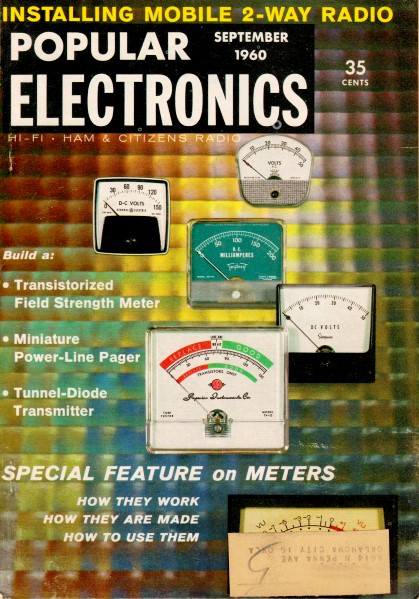
Leo Esaki invented the tunnel diode (aka the Esaki diode) in 1957 while working at Sony (Tokyo Tsushin Kogyo at the time). Tunnel diodes have a very narrow, heavily doped p−n junction only around 10 nm (100 Å) wide that exhibits a broken bandgap, where conduction band electrons on the n-side are approximately aligned with valence band holes on the p-side and thereby facilitate the quantum mechanical tunneling process after which the diode is named. A negative differential resistance in part of their operating range makes them useful for high frequency oscillators. This article in a 1960 edition of Popular Electronics introduces the device's characteristics and potential uses. It cites the price for a tunnel diode at the time to be in $5 to $15 range, with the expectation that prices will drop in the future. $5 in 1960 was the equivalent of about $44 today (per BLS). Interestingly, if you want to buy a tunnel diode today, you will likely have to find old stock on on eBay or Amazon since I could not find anyone who sells new stock (Digi-Key, Newark, Mouser, et al). Some people have used specially configured transistor circuits as negative resistance sources, but that's a lot of work and components to substitute for a diode type the industry has determined is not needed. The Tunnel Diode By Donald L. Stoner, W6TNS 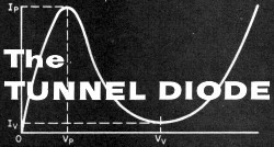 Newest of semiconductors, the tunnel diode is unique in its field. Learn why it's unique, then build a simple transmitter and put it to work. By now, just about everyone has heard of the tunnel diode, latest "miracle" from the semiconductor industry. Though related to the tube and transistor, the tunnel diode ordinarily has only two terminals. Yet it differs from other two-terminal devices (resistors, capacitors, and so on) in a very special way. Apply voltage to a resistor, for example, and you can determine current flow by Ohm's law. Increase the voltage across the resistor, and the current flow through the resistor will increase in proportion. But this is not so with the tunnel diode. The effect which brought about the practical construction of this unique semiconductor was discovered by Dr. Leo Esaki, a brilliant Japanese scientist. Dr. Esaki determined that unusual doping of the germanium-diode junction would cause the current flow to decrease, even though the applied voltage was increased. This effect, known as negative resistance, enables the tunnel diode to perform its unusual feats. Tunnel Diode Theory. To understand the term negative resistance and what causes it, let's study a more familiar object - a tetrode vacuum tube.
Fig. 1 - Tetrode vacuum tube circuit (A) displays curves (B) somewhat like those of a tunnel diode. See text.
Fig. 2 - Tunnel-diode forward characteristic curve. In negative-resistance slope range, current through diode decreases even though voltage across diode increases.
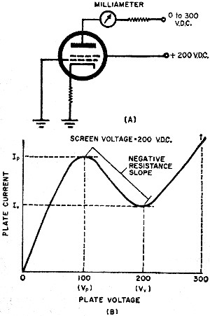
Fig. 3 - Typical crystal oscillator circuit using tunnel diode. Rint denotes internal resistance of battery.
Fig. 4 - Load line for typical tunnel-diode oscillator. Load must be as low as possible to restrict diode to negative-resistance portion of curve.
Fig. 5 - Low internal-resistance power supply for tunnel diode circuits. Drain through resistor RI is heavy but unavoidable due to required design. Figure 1(A) shows a tetrode vacuum tube with a fixed screen voltage of 200 volts and a plate voltage that can be varied between 0 and 300 volts. The tube's control grid is grounded, since we need no input signal to the tetrode for the purposes of this example. Let's vary the plate voltage between 0 and 300 volts and record the changes in the tetrode's plate current as shown on the milliammeter - see Fig. 1(B). Note that the plate current increases in the normal fashion as the plate voltage is increased until the plate voltage reaches a value of about 100 volts. At this point a peculiar phenomenon occurs due to the secondary emission from the plate - the plate current decreases as the plate voltage increases. This decrease in plate current with increase in plate voltage is called negative resistance, which is a well-known characteristic of tetrodes. When the plate voltage reaches the value of the screen voltage, 200 volts in this example, the plate current increases as before. Negative resistance is seemingly contrary to Ohm's law. If we were to apply a steadily increasing voltage across a resistor, for example, the current through the resistor would increase proportionately. If we carried this far enough, the resistor would eventually go up in smoke. But in this case, steadily increasing voltage on the tetrode's plate brings steadily decreasing current. The tetrode in this example actually exhibits a negative resistance at plate voltages between about 100 and 200 volts. Now that we know what negative resistance is, let's return to the tunnel diode. The slope of the tunnel diode's forward-characteristic curve is very much like the tetrode's plate-characteristic curve. See Fig. 2. Note that as the diode voltage is increased positively from zero to Vp, the tunnel-diode curve is similar to that for any conventional semiconductor or vacuum-tube diode. However, at Vp we reach the peak voltage of the negative- resistance portion of the tunnel-diode slope. Now the tunnel-diode current decreases as the voltage across it increases until the potential Vv, the valley voltage, is reached. At this point, the diode reverts back to type and the current increases as the voltage is increased above Vv. By operating the tunnel diode on the negative-resistance portion of its curve, we can make it function as a negative-resistance oscillator, as will the tetrode above. Typical Circuit. Figure 3 shows a typical crystal oscillator circuit made possible by the development of the tunnel diode. Actually, any negative-resistance device (a tetrode tube, operated at a plate voltage well below its screen voltage as discussed previously, for example) could be used; the arrangement is known as a negative- resistance oscillator. One of the greatest advantages of this circuit, known as a Dynatron oscillator in its tube version, is its inherent simplicity - it requires only a power source, a negative-resistance device, and a tuned circuit. Although the circuit is relatively unstable in contrast to other oscillators, its oscillatory properties depend solely on the use of a negative-resistance device between battery B1 and tuned-circuit L1-C2. Depending on the impedance of tuned-circuit L1-C2, the circuit in Fig. 3 will function as an amplifier or an oscillator. To oscillate, the diode's operating point must be in its negative-resistance region, and the impedance of L1-C2 must be greater than the negative resistance of the diode. One factor to consider with the tunnel diode is the internal resistance of the battery, Rint. This resistance is equivalent to the plate-load resistor in a vacuum-tube circuit. Figure 4 shows typical load lines that are possible for a tunnel-diode oscillator. Note that all load lines are drawn from point Vb which is the power supply voltage. The actual value of Rint is important to us. We know that the internal resistance will always be present so that a resistance of zero is impossible in practice. If Rint is too high, the tunnel diode will be operating on the positive portion of its slope, which we want to avoid. Hence, it is desirable to have a resistance as close to zero as possible. Present-day tunnel diodes have negative slope resistance between 20 and 40 ohms, and Rint should be on the order of 10 ohms or less for the oscillator circuit to operate. The action of C1 in Fig. 3 helps to reduce the internal resistance of B1. However, a low-value bleeder resistor connected in parallel with C1 would greatly improve the operation of the circuit. Figure 5 shows a low internal-resistance power supply that can be used to power tunnel-diode circuits. If you own a low-voltage power supply (one for powering transistors is ideal), it can be used in place of the circuit shown in Fig. 5. Dry cells cannot be used with much success because their voltage and internal resistance are too high. If a bleeder is placed across the dry cell, the large currents passing through the resistor will result in a steadily increasing internal resistance in the dry cell. For experimental purposes, dry cells can be used if they are of the D size or larger and are new. However, they are usable only for a short time. Building a Transmitter. For a better understanding of just what a tunnel diode can do, let's try an experimental hookup using it in a midget, or "Micro-QRP," 80- or 40-meter transmitter. Even though the tunnel diode is a low-power device, such a transmitter is capable of delivering a usable signal. The "Micro-QRP" tunnel-diode transmitter runs on about 0.6 volt at 1.8 ma., or approximately one milliwatt input. It is crystal-controlled on either the 80- or 40-meter bands, but can be used on any frequency between 3.5 and 10 mc. with the values shown. There are only nine working components in the tunnel-diode transmitter - a key jack, a 1.5-volt battery, a 1000- ohm potentiometer, a 100-ohm resistor, a .01-uf. disc capacitor, a 200-uf., 3-volt electrolytic capacitor, the tunnel diode, and a coil and crystal. See Fig. 6. Mount the components in a 1 5/8" x 2 3/4" x 2 1/8" chassis box. The meter jack is mounted on the front panel along with the bias potentiometer; the coil, crystal, and tunnel diode are mounted on the top of the chassis; the battery is located under the chassis and supported by leads soldered to the terminals.
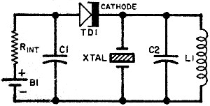
Fig. 6 - Circuit of tunnel-diode transmitter for operation between 3.5 and 10 mc. Battery power supply (shaded portion) can be replaced with supply shown in Figure 5 if desired. A large solder lug should be installed under the coil and used as the common ground terminal for the entire transmitter. It is important that both disc capacitors be returned to this point, with very short leads.
Note tunnel-diode pin connections. The meter jack is connected in an unusual manner to eliminate the need for an on-off switch. Use a two-circuit jack, with the frame grounded to the chassis. The outer contact connects to the minus end of the battery and the center contact is wired to the coil. When a meter plug is inserted, it shorts the outer pin to the chassis, thereby completing the battery circuit. The tunnel-diode circuit (through the coil) is completed by the meter. The General Electric 1N2939 and 1N2940 tunnel diodes plug into a standard transistor socket and are therefore easy to work with. The RCA TD-100, on the other hand, will have to be modified by trimming away some of the gold foil lead to make a "pin" of each terminal; be sure to remove sufficient material so that the "pin" will fit snugly in the socket gripper. Once the tunnel diode has been mounted, wire the "Micro-QRP" transmitter as shown in Fig. 6, and you're ready to check it out. Testing the Transmitter.Connect a milliammeter as shown in the schematic diagram; any meter between 5 and 15 ma. full scale will do. Turn the bias potentiometer to the minimum resistance end of rotation and plug in the meter. The reading should be a little over .01 ma. As the potentiometer is rotated, the current will increase. When the meter indicates 1-3 ma. (depending on what type tunnel diode you use), the reading will suddenly jump to a lower current. The point at which the drop occurs is called the peak current; the value to which the meter drops is called the valley current. In between these two points is the unstable or negative resistance region where the diode oscillates. By tuning a communications receiver to the crystal frequency, you should be able to hear the signal generated by the "Micro-QRP" transmitter. Place a hank of wire from the receiver antenna terminal near the transmitter, and you should be able to "peg" the "S" meter. By winding a 5-turn link of hookup wire around the coil, the transmitter can be loaded to an antenna. No claims for transmitting distance are made for the little unit, since this is almost entirely up to the skill of the experimenter.
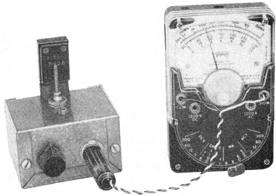
Tunnel diode transmitter is adjusted with external multimeter to determine the diode's negative-resistance region. Some tunnel diodes will not "take off" as easily as other types. Depending on your diode, you may find it necessary to touch the cathode terminal at some point between the diode and coil through a small capacitor, while adjusting the bias potentiometer. The static electricity on your body will shock-excite the transmitter circuit and start it oscillating. Once you have the circuit oscillating properly, you can adjust the coil for maximum signal. Experiments You can also use the tunnel diode to demonstrate computer switching techniques. You will find that at one particular setting of the bias potentiometer the diode will switch back and forth between the peak and valley whenever you shock-excite the anode (between the diode and potentiometer arm). Your body's static electricity acts much the same as the information fed to the diode in a computer. Although the meter moves quite slowly, the diode switches from one state to the other as fast as a bolt of lightning. In fact, the switching characteristic of this unique diode occurs almost at the speed of light - 186,000 miles per second! In computers, the tunnel diode is capable of making a "decision" in less time than it takes the light to travel from this page to your eyes! While a tunnel diode may cost you between $5.00 and $15.00 right now, it will last a lifetime (unless you step on it) and can be used each time a new circuit is brought out.
Posted December 9, 2019 |
|