Trinitron - Still a Mystery?
|
|
Explaining the workings of the Trinitron color cathode ray tube (CRT) with black and white pictures is a little like explaining the third dimension to a Flatlander. How do you visualize red, green , and blue in shades of gray? It's like being told to grasp the concept of tesseract being the 3−D projection of a 4−D cube. Still, that was the challenge author Forest Belt had when writing this article for a 1972 issue of Popular Electronics magazine, an era where multicolor print was the realm of high−end glossy−page magazines. Those of us who were around in the days when Sony's Trinitron hit the market remember well the hype that surrounded it. Of course my parent's B&W television suffered the same handicap as this printed page when the commercials attempted to demonstrate the Trinitron's color contrast and resolution superiority over traditional CRTs with a single electron gun. Once color computer CRTs were available, they also were differentiated between those that were and those that were not Trinitron types. BTW, where possible I colorized the images for your convenience. The Trinitron - Still a Mystery?
Despite a rash of advertising, there are still people who don't know what a Trinitron is. A few think it's some kind of TV set. Others know it's something special from Sony, but they're not sure what. The Trinitron is a picture tube for color television. Sony introduced the first color receiver using a Trinitron several years ago, a 7-inch model that never got into production. But more recently, both 9- and 12-inch versions have been imported in quantity. And just this past winter, a 17-inch model appeared in the U.S. The "large-screen" Trinitron resembles its predecessors, but incorporates definite changes.
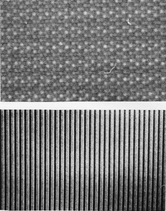
Fig. 1 - Standard triad dot pattern (top) and Trinitron stripe pattern.
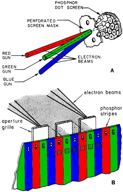
Fig. 2 - At top is shadow mask scheme; below, Trinitron CRT aperture grille.
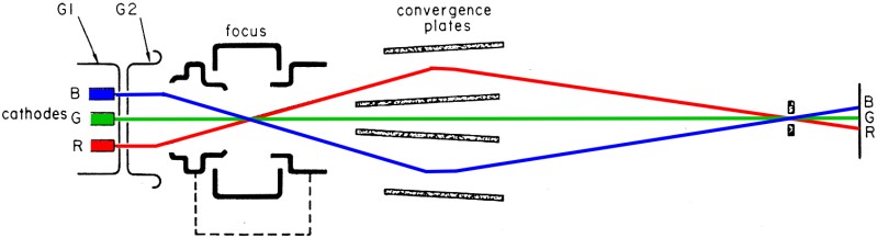
Fig. 3 - The gun in a Trinitron emits and controls all three color beams; in ordinary color-TV picture tube, three separate guns are used to make beams.
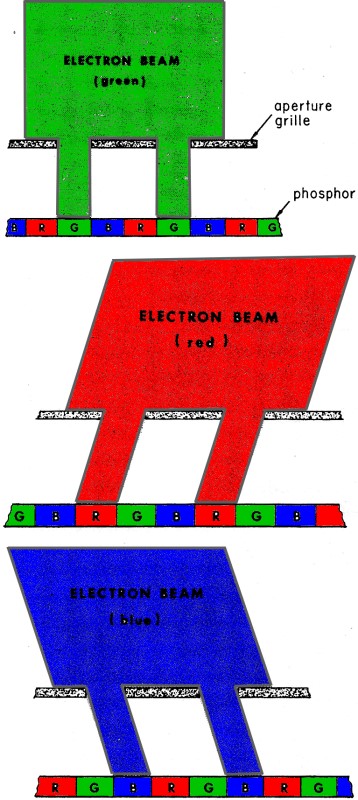
Fig. 4 - In Trinitron, the angle of each beam determines which phosphor it hits. Beam is larger than stripes; so that it hits two at the same time. The Trinitron CRT is touted as being simpler than American color tubes. The advantage isn't all that obvious to a viewer; but inside the cabinet, the Trinitron operates with comparatively few circuits. For example: Any color set has critical adjustments to register the primary red, blue, and green rasters accurately on top of each other. The term is convergence, and the object is to keep colors from fringing black-and-white pictures. An ordinary color set, American or Japanese, has seventeen convergence adjustments. A receiver using the Trinitron has only a half-dozen or so. Credit for simplification goes to the way the Trinitron picture tube is structured. It differs from the usual picture tube in several important ways: (1) The Trinitron phosphor screen is deposited in narrow vertical stripes instead of tiny dots. (2) The mask behind the Trinitron phosphor is a grille of vertical slots instead of a shadow mask of round holes. (3) The Trinitron emits three beams, one for each primary color, but from only one electron gun; the ordinary color CRT has three separate guns. (4) The beams in a Trinitron are side-by-side whereas in a conventional color tube they are spaced in a triangular relationship. (5) Special plates converge Trinitron beams electrostatically; a conventional color CRT converges electromagnetically, with a yoke of coils around the neck of the tube. (The newer large-screen Trinitron uses a convergence yoke, controlled by only three adjustments.) Stripes Instead of Dots. First, consider the phosphor. Compare the two photos in Fig. 1. The dots arranged triangularly belong to the phosphor of a conventional color tube. Each triad of dots contains one red dot, one green, and one blue. The stripes in the other photo are a Trinitron phosphor. Each stripe is one color. They line up red, green, blue, red, green, blue, and so on. Either kind of phosphor needs some sort of mask between it and the source of the beams. Otherwise, any electron beam could "splatter" onto adjacent dots or stripes, thus activating the wrong color. In the conventional picture tube, a perforated metal screen (Fig. 2A) confines the size of each beam. Because the metal sheet "shades" the edges of the beams, the name shadowmask has become accepted. The Trinitron electron beams get similar treatment. The masking metal screen (Fig. 2B) contains vertical slots rather than round holes. Sony calls the mask an aperture grille. The phosphor stripes are very narrow compared to the beams. Each beam spreads across two slots in the grille. But the angle at which each beam strikes the grille slot nevertheless directs it to the correct phosphor stripes. How this works is illustrated in Figs. 3 and 4. Back in the Trinitron electron gun, the red and blue beams bend, cross, and aim outward, while the green beam remains straight. As they pass between the convergence plates, the red and blue beams are directed back toward the center axis. If convergence is correct, all three beams cross again precisely at the aperture grille. You can see the effect on individual beams in Fig. 4. The green beam, coming through straight, strikes the slotted masking grille exactly perpendicular. The wide beam spreads over two of the aperture slots - and then some - but the metallic grille blocks all except what can get through those two slots. The aperture grille positioning lets the green beam straight through to illuminate two green phosphor stripes. The red beam, having been bent outward and then back inward, strikes the aperture grille from an angle. The slots - the same ones that let two green beam-segments through - pass only enough red beam to illuminate two red stripes of phosphor. The angle of the red beam just suits the positioning of the red stripes with respect to the grille openings, and the red beam does not touch green or blue stripes. The blue beam approaches from the angle opposite the red. The slotted aperture passes two beams just wide enough, and at the correct angle, to hit only blue phosphor stripes. Of course, all the while, the three beams are being swept from side to side and from top to bottom to form a raster. As you view the front of the Trinitron picture tube, the picture looks about like it does on any regular color CRT - unless you inspect it closely. Then you can see the individual lighted vertical stripes, just as you can see individual phosphor dots on the screen of a conventional color tube if you look closely. Three From One. The sketch in Fig. 3 shows the gun structure of a Trinitron. Conventional color picture tubes have three separate electron guns, each with its own heater, cathode, grid 1, grid 2, and focus anode. The three heaters share common base connections, and all three focus anodes go to one base pin. But the other elements in all three guns have their separate base connections. In early Trinitrons - the 9- and 12-inch - only the cathodes are separate. Grid 1 is common to all three cathodes, and thus controls the intensity of all three beams Simultaneously. You can imagine how this trims grid-circuit requirements. Only one pin connection serves all three beams. And grid 2 circuitry is cut two-thirds also, since the G2 pin is common to red, green, and blue beams. Focus circuitry differs from that in conventional color sets, but not in number of connections. Ordinary color CRT's require several thousand volts for focus. Not so, the Trinitron. Only a few hundred volts is needed. Focus supply circuitry can therefore be simple by comparison. And Easy Adjusting. Beyond the novelty of generating and controlling three electron beams with only one gun, the Trinitron's most spectacular advantage lies in convergence. In 9- and 12-inch Trinitrons, special plates control the crossover point for the three beams. Ideally, crossover occurs precisely at the aperture slot. A high-voltage dc field between the convergence plates bends the beams accurately while they are aimed at the center of the phosphor screen. But remember, the beams are constantly being swept back and forth. To make sure they cross accurately out near the edges, a special signal voltage (parabolic in shape) also drives the convergence plates. Timed to fit each horizontal sweep, the parabolic signal adapts convergence crossover to the curvature of the phosphor screen and aperture grille. Compared to a typical color tube, the Trinitron converges with extreme simplicity. Because the phosphor is striped instead of dotted, slight vertical misconvergence hardly matters. So, adjustments are reduced to a bare minimum. Once mechanical (static) convergence is adjusted with four neck magnets, a mere two controls shape the parabolic signal for dynamic convergence. It takes four magnets plus thirteen controls to converge other color tubes. A new 17-inch Trinitron gives up some of the simplicity of small-screen models. For one thing, the electron gun is more complicated. Each cathode has a control grid (G1) of its own. That necessitates extra circuits, and alterations in the way video and color signals are fed to the Trinitron. Otherwise, the gun in the larger Trinitron hasn't been changed much. Scanning the wider screen also brought problems that necessitate more elaborate convergence. The plates inside the tube still get high dc for basic convergence, but no parabolic signal. Instead the 17-inch Trinitron has a small yoke of convergence coils around the picture tube neck. Even so, adjustments are much simpler than for conventional picture tubes. A mere half-dozen controls does the entire job. Whither Color CRT's? The Trinitron is the first drastic change in picture-tube technology since color television came on the market. It represents a major step toward making color receivers easier to adjust and repair. Trinitron chassis represent the start of a design trend to minimize critical stages, which in the long run eliminates nuisance maladjustment. Other sections of both color and monochrome receivers could benefit from similar attention. Meanwhile, what else can be done for picture tubes? The most sought-after innovation is a flat screen, with little thickness. The Trinitron design boasts short neck length as well as small neck diameter. But the front-to-back dimension of Trinitron receivers subtracts little from other designs. Whoever comes up with a picture tube under 6 inches from screen to socket will have taken a giant step toward the ideal of a hang-on-the-wall color picture tube.
Posted May 25, 2023 Color and Monochrome (B&W) Television Articles
|
|

 By Forest H. Belt