How to Stack TV Antennas to Increase Signal Strength and to Reduce Ghosts
|
|
Update: See Mr. Dave Jones' stacked TV antenna project that used information in this article for phasing dimensions. How to Stack TV Antennas to Increase Signal Strength and to Reduce GhostsBy Lon Cantor, Jerrold Electronics Corp.
However, increasing signal strength isn't the only reason for stacking antennas. In fact, it isn't even the best reason. If you need more signal pickup, you may be better off buying a more expensive, higher gain antenna than stacking two antennas. And, if even the best antenna you can find doesn't do the job, you should probably add a good mast-mounted preamplifier. When should you stack antennas? When you are faced with certain reception problems that can't be solved in any other way. There are two ways to stack antennas: vertically and horizontally. Vertical Stacking. There are three reasons for stacking antennas vertically: (1) To reduce signal fading from distant TV stations; (2) To reduce airplane flutter; (3) To increase signal pickup. Because TV signals are so high in frequency, they are limited primarily to line-of-sight distances. However, by various means, they do manage to get to "blind" areas and regions a short distance over the horizon. While lower frequency radio waves do follow the curvature of the earth and TV signals don't bend very well, a small portion of the TV signal does bend around obstructions to get to the antenna. This can take the form of a knife-edge type of diffraction as from the roof-edge of a building, or a gentler slope as from the top of a hill. Television signals also reach the fringe antenna by reflection-bouncing off of atmospheric interfaces, and refraction-bending caused by atmospheric layers with different densities. Let's suppose you're putting up a fringe antenna. You won't get the most signal just by mounting the antenna as high as possible. Instead, you must carefully probe for the height that gives you the best possible TV pictures. Because of the methods of signal propagation, this height is quite critical. It is the height at which most of the diffracted, reflected, and refracted signals that are present arrive in phase. At heights at which these various signals arrive out of phase, they actually subtract from each other. The trouble is that the signals that reach the antenna by atmospheric reflection and refraction are not stable. They change as the atmosphere shifts. This is the main reason for signal fading in fringe areas. The solution to this problem is the vertical stack. You put the two antennas at different heights. Thus, when one antenna is receiving out-of-phase signals, the other is receiving in-phase signals. If you combine these two antennas properly, you wind up with an average signal that doesn't vary much. This is a form of diversity reception.
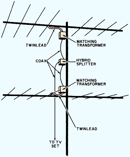
Fig. 1. Hybrid splitter allows signals from each antenna to add to each other, and minimizes loss when one antenna acts as a load on the other. Leads to transformers and splitter should be equal.
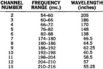
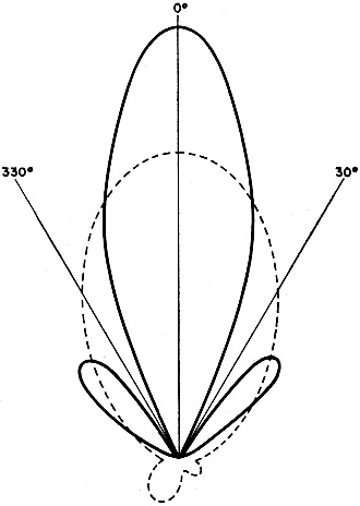
Fig. 2. Select wavelength of lowest channel to adjust space between stacked antennas to prevent mutual interference. Two-thirds wavelength is minimum. When the antennas are not delivering the same signal, the out-of-phase antenna acts as a load to the in-phase antenna. Instead of getting additional signal, you actually get less than the in-phase antenna alone can deliver, unless you effectively isolate one antenna from the other. Commercially available stacking bars won't do the job. Stacking bars are fine when both antennas are delivering approximately the same signal. Obviously, this is seldom the case in a fringe installation. Figure 1 shows how antennas should be vertically stacked to minimize signal fading. There are five important things to do to make a good vertical stack. (1) Use identical antennas. (2) If you use coaxial cable, such as RG-59/U, you should also use a weather-proof 300-ohm to 75-ohm matching transformer mounted as close as possible to each antenna. (3) Use a hybrid type splitter. This type of unit is like a one-way valve. The output contains the sum of the two inputs, with virtually no loss. Yet the two inputs are isolated from each other. Even if the signal on one antenna goes down to zero, it cannot subtract more than about 10% of the signal from the other antenna. (4) Space the antennas at least two-thirds of a wavelength away from each other on the mast. A full wavelength is preferred, but this is not always possible. In calculating this distance, use the wavelength of the lowest channel in your area. Figure 2 shows the wavelengths of all the VHF channels. (5) Make the harness symmetrical. The lead run between each antenna and its matching transformer must be identical. Similarly, you must use equal lengths of cable between each matching transformer and the hybrid splitter. Horizontal Stacking. It is foolish to use a horizontal stack simply to increase signal pickup. It is easier, cheaper, and just as effective to use a vertical stack for this purpose. Horizontal stacks, however, may be the only possible way to do the following things: (1) To reject ghosts; (2) To minimize co-channel interference; (3) To minimize adjacent-channel interference; (4) To reduce man-made interference. Figure 3 shows the reception pattern of one log-periodic antenna, compared with that of two of them horizontally stacked. Notice that stacking not only increased gain, but changed the pattern considerably. The stacked pattern shows two side lobes, although there are others, with nulls in between. These nulls are important. You can use them to get rid of unwanted signals. The pattern shown in Fig. 3 is for one particular horizontal stacking situation: when the antennas are stacked precisely one wavelength apart (center to center). Notice that under these conditions nulls are produced at 30° to the right and left of 0°.
Fig. 3. Angle of null points can be changed by adjusting the spacing between horizontally stacked antennas (solid line) to drop out interference. Dotted line is response curve of single antenna. Now, suppose you had a tall tower reflecting a ghost signal from an angle 30° away from the transmitted signal. You would simply aim the two antennas at the transmitter, the ghost would conveniently fall into the null, and you'd never see it on the TV screen. It is seldom, however, that you can count on unwanted signals coming in from precisely one of those angles. Therefore, you have to find a method of varying the angles of the nulls. Fortunately, this is quite simple. All you have to do is vary the horizontal spacing between the antennas. And you don't need any complicated formulas or measurements, either. The trial and error method works best. Before you start shifting the antennas, you should construct a symmetrical harness - same type leads, lengths, and matching transformers - between the hybrid splitter and the antennas. Point both antennas directly at the transmitter. Keeping them parallel, slowly move one antenna closer to, or away from, the other. While you are doing this, you need someone to watch the TV set for a sudden, sharp reduction in the unwanted signal. Secure the antenna in this position. The unwanted signal may still be noticeable in spite of the sharp reduction. But, you're not through yet. Remember that the unwanted signal must appear as equal and opposite polarity voltages to cancel out. By finding the correct horizontal spacing, you've made sure that the unwanted signal arrives at the two antennas 180° out-of-phase. Now, you must make sure the signals are equal. To do this, simply move one antenna up and down on the mast while someone again watches the screen. Secure the antenna at the point where the unwanted signal is weakest. Horizontal stacking is used to clean up master TV antenna systems, and it works just as well in home TV installations - especially color installations.
Posted April 3, 2024 |
|