Space Electronics
|
|
The late 1950s and early 1960s were the dawn of the Space Age, beginning unofficially with the launch of Sputnik. Popular Electronics magazine put a lot of effort into educating the public on advances in space electronics, including not just the spaceborne platforms, but also ground tracking and communicating equipment. Much hardware was launched into orbit in the early years without giving much thought to the hazards or space debris. Failures in the form of explosions scattered chunks widely, but fortunately most were low enough to have their orbits degrade and re-enter the atmosphere. One interesting tidbit reported in this article that I didn't know was that the TV camera lens on the TIROS 2 weather satellite was defocused during launch (due to positional shifting from vibration and G forces, I suppose) and crippled the image quality severely. Space Electronics
The National Aeronautics and Space Administration has proposed sending seven spacecraft to the moon in 1963 - 1965. Given the code name, "Surveyor," these fully automatic satellites will soft-land on the moon and send back TV pictures of the surface. They will also conduct a number of other experiments to determine the content and texture of the lunar surface. The model shown here was developed by Hughes Aircraft.
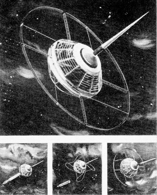
As this column goes to press, a Juno II is being readied at Cape Canaveral. The payload is now called NASA S-45, but if the shot is successful it will become Explorer X. Destined to study the ionosphere, this unusual satellite will transmit on six different radio frequencies. The ring antenna will be used on the lower frequencies - it is designed to unfold after separation from the fourth stage.
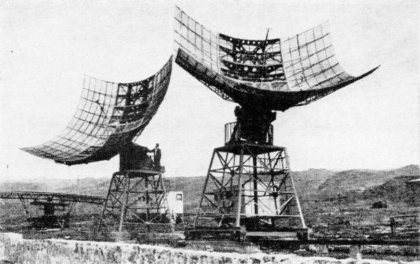
These Soviet radio-telescope antennas are located in the Caucasus Mountains. Similar antennas are probably used to operate the telemetering transmitters on LUNIK IV. SOVFOTO
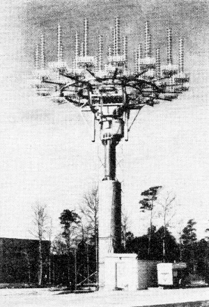
One method of satellite tracking. General Electric's optical tracker using a high-power telescope and special TV image pickup tube. Another method of satellite tracking. The new 33 element helical beam antenna at Wallops Space Flight Station.
"In short, my plan is to develop the XM-7 rocket ourselves, launch it in 18 months, and claim Mars in the name of the Meredith Aircraft Corporation." Only the rocket engines and propellants outrank electronics in importance. But even this is questionable - for without electronic guidance a rocket would never get to the right place at the right time. And, even it it did, how would we earthlings know it? In short, without electronics, there could be no space program. Recognizing this "truth," the editors of Popular Electronics plan to devote several pages each month to Space Electronics. Can anyone hear satellites? This is the question most frequently asked by SWL'ers, experimenters, hams, and novices in space science. The answer is a very simple "yes." Many satellite signals-both American and Soviet - have been heard by curious listeners. In fact, as we shall show in one of our forthcoming columns, SWL-type verifications have been issued for about ten satellites. The Soviet satellite signals have been consistently easier to intercept. All of the Lunik and Sputnik satellites have had at least one transmitter operating within plus or minus 20 kilocycles of 20 megacycles (19.98 mc.-20.02 mc.). The listener need only spot the 20-mc. broadcast from Station WWV on the dial of an average short-wave receiver. He can then sit back and wait, for some time within the following two hours he will have a good chance of hearing a Soviet satellite. Most listeners have been distressed to find that practically all of the American satellites transmit on frequencies near 108 megacycles. The power radiated by them has been low, generally less than 1/2 watt. However, many experimenters and radio amateurs, using modified FM converters and simple two- or three-element beams, have been able to verify American satellite radio transmissions. Radio Signals from the Satellites
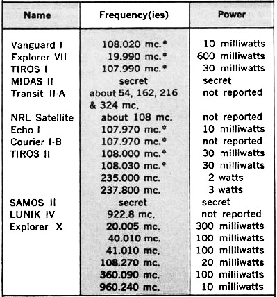
Satellites are listed in the order launched. Explorer X had not been launched at press time. but is included because of number and variety of frequencies to be employed. Asterisk indicates that this is the beacon transmitter frequency. But the listener must know when to listen and what to listen for. It is impossible in this first installment to discuss all the ways and means of knowing when to listen. Simplified methods are available to permit satellite tracking -when one or two check positions and the date and time of the launching are known. These methods will also be discussed in detail in one of our forthcoming columns. In the meantime, the table at left contains information on the frequencies and radiated power of the satellites known to be in orbit and transmitting as of February 20, 1961. FM/TV DX Reflections The 100-foot balloon (called Echo I) that is now circling our globe presents another possibility for DX'ing the FM/TV bands. Using the same principle as the Bell Telephone Laboratories in communicating between Holmdel, N. J., and Goldstone, Calif., that is, ignoring the earth's ionosphere and bouncing the signal off the satellite, a DX'er may be able to catch rare FM and TV signals. The DX'er should spot his receiver on an unoccupied channel and await a satellite passage. As the satellite approaches overhead, midway between the distant transmitter (say 1000-2000 miles) and his receiver, there should be a "burst" of signal. Under average conditions it would not be unreasonable to expect to hear 25-30 seconds of an FM or TV signal - certainly enough during station break time for identification purposes. Radio amateurs have not been able to use Echo I consistently because of the relatively weak power they are permitted to radiate. Even with highly directive antennas, their "effective radiated power" is always under 50,000 watts. Many TV and FM transmitters, on the other hand, are operating with an "effective" power above 350,000 watts. If the FM/TV DX'er uses a modest beam of only 6-db gain, however, he can work with "effective" powers near 1 megawatt! "Passive" Satellites Although there is much to be said for the "active satellite" which receives and transmits like a miniature relay station, many scientists are convinced that passive reflecting satellites have a definite place in the U. S. space program. The National Aeronautics and Space Administration (NASA) has plans to orbit another Echo-type balloon with about twice the reflective power of Echo I. This extra gain will result from increased size and reflectivity of the Mylar-aluminum foil surface. Another line of thought concerning the Echo-type balloon is that such passive communication satellites should be anything but spherical reflectors. The U. S. Air Force has been studying unusual passive satellite designs that would be "100 times" more efficient in reflecting power than Echo I. It is interesting to note that if the latter experiments prove successful, FM and TV DX will become rather commonplace. Space Facts The Missile and Space Vehicle Department of the General Electric Company is currently distributing a comprehensive booklet on space data. Entitled "Space Facts," this 64-page booklet is jam-packed with figures, tables, and charts on the earth's atmosphere (how much, how far into space, etc.), the physics of space flight ( orbit decay, thrust, re-entry problems, etc.), and bioastronautics (acceleration, impact, etc.). One section is devoted to space communications, and shows the eight basic means of earth-to-space vehicle or satellite-to-satellite radio links. Distant range of one-way communication may be calculated from a fold-out table bound in the booklet. Space Facts is really a handbook written for technicians and engineers who need basic information at their finger-tips. Offered free (write Space Facts, Missile & Vehicle Dept., General Electric Co., 3189 Chestnut St., Philadelphia 4, Pa., Att. Mr. J. Hoffman), it will undoubtedly be in short supply. First come - first served. Satellite Briefings One of the many disappointments due to the failure of Pioneer VI (the projected lunar probe that exploded 70 seconds after launching on December 15, 1960) was the fact that a General Electric satellite tracking device had no chance to be tested. An optical tracker using a special TV camera tube attached to a high-power telescope, this G. E. system is so sensitive that it can take movies at night using only starlight. Following Pioneer VI to a lunar orbit would have been roughly equal to spotting something the diameter of a dime at a distance of 2500 miles! The transmitters aboard TIROS II may be inactive by the time this column is in print - original plan for battery life was about 4 months, and TIROS II was launched on November 23, 1960. Both wide and narrow-angle TV camera lenses were present in the TIROS II, but the wide-angle TV lens was defocused during launching and only 86% (9524) of the photos relayed to earth are proving useful for weather analysis. Although the narrow-angle TV transmitter performed excellently, the photos are of comparatively little value without the orientation obtainable with the wide-angle lens. TIROS II also used a simple magnetic system to control the satellite spin axis, enabling ground observers to change the angle of the axis in space. The system was developed by RCA in cooperation with NASA.
Posted January 24, 2023 |
|
 Have you ever stopped to think where our satellite program would be without electronics?
The answer obviously is "nowhere." Without radio signals, for example, our satellites
would be big chunks of scrap metal floating around in space.
Have you ever stopped to think where our satellite program would be without electronics?
The answer obviously is "nowhere." Without radio signals, for example, our satellites
would be big chunks of scrap metal floating around in space.