A Primer on Single Sideband
|
|
Single-sideband (SSB) modulation was a big deal when it was first introduced at a time when the radio spectrum was getting pretty crowded - particularly in the commercial broadcast bands. It allowed more channels / stations to be packed into available space, which was obviously a good thing, but the other main benefit of SSB is the transmission efficiency - especially when a suppressed carrier format is used. At really high powers, electronic components, antennas, cabling, and facilities are very expensive, so being able to broadcast a signal over a given distance at a lower power represents a cost savings. As the old saying goes, though, "there is no free lunch." Modulators in transmitters require more circuitry and much be kept in alignment in order to properly operate in single sideband mode. Receivers, too, are more complex as the requirement for carrier recovery (for suppressed carrier SSB) and other accommodations are needed. This article from a 1974 issue of Popular Electronics magazine does a great job of introducing the uninitiated into the world of single sideband. Methods of SSB signal generation, transmission and reception
Single-Sideband, or SSB, modulation has begun to supplant conventional amplitude modulation (AM) in electronics communication. Many military and commercial systems have made the switch. So, too, have a great many amateur radio operators. More recently, Citizens Banders have joined the ranks of the SSB communicators. SSB modulation has distinct advantages in communications. One of the most important is its inherent conservation of the crowded frequency spectrum. When compared to conventional AM, SSB requires only half the spectrum space, in effect doubling the number of channels i n a given portion of the frequency band. A good example of this is the 27-MHz CB band where only 23 channels are available with AM, while 46 channels of SSB fit into the same band.
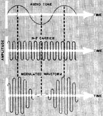
Fig. 1 - In amplitude modulation, audio tone (top) combines with r-f carrier (center) to produce waveform at bottom whose envelope varies in amplitude and frequency with the audio tone. SSB is also much more efficient than AM. In AM, most of the power is concentrated in the r-f carrier. By contrast, SSB suppresses the carrier and concentrates most of the power in the information-bearing sideband signal. This, coupled with greater immunity to selective fading, gives SSB communication much greater "talk power" than is possible with conventional modulation techniques. The Basis of SSB To transmit a signal over a given distance, information is imposed on a r-f wave. The r-f wave serves as a "carrier" - hence its name - for the lower-frequency information. Successful communication results from proper utilization of the frequency-dependent properties of the carrier, as well as efficient use of the transmitted energy. The information can be imposed on the r-f wave by modifying, or modulating, the carrier as the result of varying the carrier's frequency or amplitude (or both). Frequency modulation (FM) and amplitude modulation (AM) and simultaneous amplitude and frequency modulation (AM/FM) can take a wide variety of forms. AM in its basic form is perhaps the easiest to produce. To impress an audio-frequency (a-f) modulation on a r-f carrier, the carrier is made to vary in amplitude according to the instantaneous amplitude of the a-f signal by a process known as "mixing." In Fig. 1, the audio and carrier waveforms are combined to produce the modulated r-f wave shown at the bottom. Notice that the relative peak-to-peak amplitude of the modulated wave varies in accordance with the relative amplitude of the modulating audio. Mathematically, the amplitude-modulated signal contains several discrete frequencies for any given carrier and audio inputs. As shown in Fig. 2A, the output consists primarily of the original and carrier signals, plus two additional mixing products whose frequencies are the sum and difference of the a-f and r-f signals. Called "side tones," these two frequencies are equally spaced on either side of the r-f carrier's frequency. (There are many other mixing products, including harmonics of the inputs and outputs and their mixing products, but these are almost negligible and need not be considered in this discussion.) When the audio input is of varying frequency and amplitude, as is the case with voice, the side tones vary in strict accordance, producing what may be termed "sidebands" on either side of the carrier. The sidebands form the characteristic "envelope" of the modulated waveform. These sidebands contain all the original audio information and are essentially mirror images of each other. With 100-percent modulation, the carrier contains twice as much power as the total in both sidebands, yet the carrier conveys no usable information. Also, since the sidebands are mirror images of each other, only one is needed for effective communication. This means that what remaining power there is must be divided between the two sidebands. Hence, under the very best of modulating conditions in AM, less than 25 percent of the available power goes into the information signal.
Fig. 2 - Frequency components of AM and SSB signals are shown in (A) and (B), respectively.
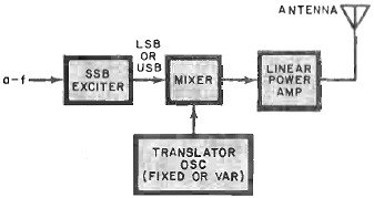
Fig. 3 - Basic block diagram of SSB transmitter. In SSB communications, one sideband and virtually all of the carrier are eliminated. After all, the audio signal already has both frequency and intensity. The frequency information is transmitted as the difference between the carrier reference and side tone frequencies. The intensity information is characterized by the amplitude of the side tone. So, one sideband of an amplitude-modulated wave can carry the audio signal if the reference frequency of the original carrier is available. The suppression of the carrier and elimination of one sideband permits all of the available power to be concentrated in the information-bearing signal (see Fig. 2B), effectively multiplying power efficiency while halving the bandwidth required. An interesting aspect of the SSB signal is that it disappears when there is no modulation. (In conventional AM, the carrier is present regardless of whether or not it is modulated. In other words, the carrier has accompanying sidebands only when modulated.) In SSB, filtering out all but one sideband causes the sideband to disappear when modulation ceases. The SSB Exciter Unlike conventional AM, the SSB signal is usually generated at a low power level in separate transmitter stage known as an "exciter." SSB signal generation is easier to accomplish at a fixed frequency. The output of the exciter is translated in a mixer to the desired transmit frequency and is then amplified to the desired power level. (See Fig. 3.) The balanced modulator, a type of mixer that suppresses the carrier at its output, is basic to the SSB exciter. The basic types of balanced modulators shown in Fig..4 include shunt, series, and ring (or double-balanced) types. The shunt and series types may contain two or four diodes, with the latter versions often referred to as "bridge" or "quad" modulators. The operation of the balanced modulator can be visualized as an audio signal being switched on and off at the rate (frequency) of the r-f carrier. If the modulator is in balance, the carrier is cancelled at the output and only the two sidebands remain. Balancing of the modulator is achieved by close matching of the diodes and by trimming. In a properly designed and balanced circuit, carrier suppression can be as much as 50 dB. The ring modulator provides good carrier suppression with higher output voltages and lower unwanted mixing products than both the shunt and series modulators. After the double-sideband (DSB) suppressed-carrier signal is generated in the balanced modulator, one of the sidebands must be eliminated by filtering,. This is no easy task because the two sidebands are very close together in frequency. If the lowest modulating frequency is 300 Hz, the sidebands will be only 600 Hz apart. Hence, filtering must be accomplished by a very high-Q filter with a narrow passband and steep side skirts. A relative comparison between an ideal filter, a multiple-pole crystal or ceramic lattice filter, and an ordinary LC filter is shown in Fig. 5A. From the evidence of the curves, it is obvious why a crystal or ceramic filter is the usual choice in SSB.
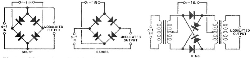
Fig. 4 - In SSB, carrier and r-f signals are mixed in balanced modulators. Outputs have suppressed carriers.
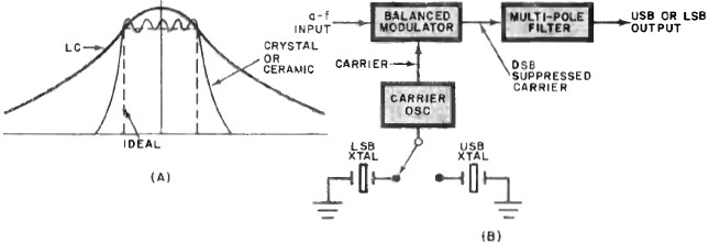
Fig. 5 - Relative comparison between ideal, crystal or ceramic and LC filters shown at (A). (B) shows elements of SSB exciter. Since the filter is designed for a fixed frequency, some method must be used to permit selection between the upper sideband (USB) and lower sideband (LSB). Two expensive filters can be used, but it is simpler and more economical to switch the carrier frequency input to the balanced modulator. For example, if the filter's output is the USB signal, the carrier oscillator can simply be raised by a fixed amount (usually 3 kHz) so that the LSB signal is at the filter's frequency. The carrier oscillator is usually crystal controlled. So, the change from USB to LSB and vice versa can be easily accomplished by switching crystals as shown in Fig. 5B. The "phasing" exciter is another type sometimes encountered in SSB. It has two balanced modulators and two phase-shift networks, one for audio and the other for the carrier. The modulator outputs are combined in such a manner that one sideband is reinforced while the other is cancelled. This scheme requires critical phasing for each frequency if no frequency translator is provided. Another disadvantage is that circuit complexity is considerably greater than with the filter method. Frequency Conversion Since filter requirements force the exciter to operate at a fixed frequency, a converter must be used to translate the exciter's output to the operating frequency. The converter consists of a mixer with a tuned output and an oscillator that can be either fixed or variable, depending on the requirements. The mixer produces the sum and difference products of the output of the exciter and the converter oscillator. The tuned mixer output passes the mixer product at the transmitter frequency. To illustrate this process, refer to Fig. 6. Here, a 9-MHz SSB signal, mixed with a 19-MHz crystal oscillator frequency, produces sum and difference products at 10 and 28 MHz. The tuned output allows only the 28-MHz signal to pass. The 28-MHz signal has acquired the SSB-modulation from the 9-MHz exciter output. The signal can now be amplified and transmitted. The conversion from 9 to 28 MHz is referred to as "up-conversion." Similarly, "down-conversion" can be used to convert from 9 MHz to, say, 7 MHz. If a band of frequencies, such as from 28.0, to 28.5 MHz, must be covered, switching crystals from 19.0 to 19.5 MHZ could be used in the converter. However, this can become cumbersome if many frequencies are required. Frequently, a variable-frequency oscillator (vfo) is substituted in the converter to allow continuous coverage of a given frequency increment. A vfo with a 500-kHz range from 19.0 to 19.5 MHz would do the job, but it must be very stable to obviate any drift in frequency. The converter provides two choices for the oscillator frequency that will produce the desired output. In the above example, a 37-MHz oscillator would produce primary mixing products of 28 and 46 MHz. The choice between the two oscillator frequencies is based on a number of factors, including oscillator stability, mixer efficiency, crystal stability, and cost. If the difference product is selected, as in the 37-MHz case, an inversion of the sideband occurs. This means that, if the 9-MHz exciter output was USB, the converter, output produced by subtracting 9. MHz from 37 MHz would be the 28-MHz LSB. This phenomenon does not occur when the sum product is selected. Linear Amplifiers
Fig. 6 - Typical converter stage translates exciter output to desired transmit frequency.
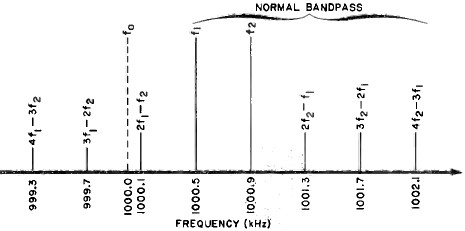
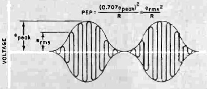
Fig. 7 - Distortion products created by r.f. amplifier nonlinearities create "splatter" on adjacent frequencies. Once the SSB signal at the proper frequency is generated, it must be amplified to the desired output power level. Both AM and SSB signals can be severely distorted by any nonlinearities in the driver or power amplifiers. In an AM transmitter, this problem is usually avoided by modulating the carrier in the final r-f stage. This "high-level" modulation cannot be used in an SSB transmitter where a low-level exciter signal must be greatly amplified. For this reason, it is important that amplifier stages be extremely linear to limit distortion to an absolute minimum. The distortion products created by amplifier nonlinearities can appear in and around the SSB signal at appreciable power levels. Distortion products are produced by means similar to those in the mixer. To illustrate, if a two-tone 500- and 900-Hz test signal were applied to the audio input using a 1000.0-kHz USB signal, the modulation would appear at 1000.5 and 1000.9 kHz. In Fig. 7,. the lower-order distortion products resulting from harmonic mixing are shown. Notice that some of these products are within the normal bandpass and others are adjacent to it. These spurious outputs can cause significant interference to adjacent channels and, if distortion is very bad, even frequencies far removed. There is another common source of distortion that can be confused with power amplifier nonlinearity. This is distortion at the audio input due to either excessive clipping or compression in the audio stages or overmodulation. The two-tone signal can also be used for determining the power contained in an SSB signal. The waveform of a two-tone SSB signal is shown in Fig. 9.The signal is rated in peak-envelope power (pep) developed by two tones of equal amplitude. Pep can be calculated by squaring the rms value of the peak, envelope voltage Ep and dividing the result, by load resistance R (pep = Ep2/R). In the two-tone case, the pep is twice the average power dissipated in the load. Receiving SSB The SSB receiver is similar to any other superheterodyne receiver (see Fig. 9). Nonlinearities in the r-f or i-f amplifiers will cause distortion in the SSB receiver just as they will in the AM receiver. Distortion due to overloading the amplifier is reduced by the automatic gain control (agc). The agc must be designed differently for SSB reception. Unlike AM where the carrier is present even when there is no modulation, the SSB signal disappears completely in the absence of modulation. For this reason, the agc must reduce amplifier gain quickly when it first senses a strong SSB signal and increase the gain very slowly when the signal disappears. This fast-attack, slow-release response compensates for short pauses in conversation. In some receivers, the sustaining time of the agc can be adjusted as desired.
Fig. 8 - Diagram shows how two-tone SSB envelope can be used to calculate pep of SSB signal.
Fig. 9 - Basic SSB receiver is similar to other superhets. Note crystal switch to select sideband.
Fig. 10 - Two examples of types of product detectors that are used in SSB signal demodulation. The r-f amplifier, mixer, and local oscillator are similar to the circuits found in AM receivers. The i-f amplifier, however, can be much narrower in bandpass since the SSB signal is less than half the bandwidth of an AM signal. Reducing i-f bandwidth has the added advantage of reducing the total noise power presented to the detector. Frequently, the local oscillator frequency is selected so that the high-Q mechanical or crystal filter in the SSB exciter can also serve as the i-f filter. SSB demodulation is radically different from AM detection. As mentioned earlier, the SSB signal varies in frequency from a reference, depending on the modulating signal frequency. The reference was originally supplied by the r-f carrier. That reference carrier must again be simulated to provide something with which to compare the SSB signal frequency. Thus, the receiver must inject a simulated carrier into the detector by means of a carrier-reinsertion oscillator or beat-frequency oscillator (bfo). The bfo is usually crystal controlled to maintain a high order of stability. The proper bfo frequency depends on whether the signal to be received is USB or LSB. In the case of USB, the bfo frequency must be lower than the signal frequency, while for LSB it must be higher than the signal frequency. Crystal switching changes the bfo from the lower edge of the i-f passband to the upper edge to receive USB or LSB. The actual process of detection can occur in an AM-type integrating detector after the bfo signal is injected. But much higher quality detection can be obtained with a "product detector." (Examples of product detectors are shown in Fig. 10.) The quality of the received audio depends to a large extent on how dose the reinserted carrier is to the frequency of the original carrier. To allow for same drift or misalignment between the transmitted signal and the receiver's local oscillator and bfo, a means of adjusting one or both oscillators must be included. A trimmer for either oscillator might go under various names, the two most popular being "fine tuning control" and, in the case of CB radio, "clarifier." In some sophisticated receivers, this function is accomplished by an automatic-frequency control, similar in function to the afc circuit used in FM receivers. Without the aforementioned control, speech would be unintelligible. In Conclusion The use of SSB modulation offers distinct advantages for the modern communicator. Especially in the high-frequency bands, SSB conserves valuable spectrum space. Where the total output power (or input power to the transmitter's final amplifier) is limited by government regulation, SSB packs all the power into one no-nonsense information signal to provide greater communicating range and reliability. If maximum power is limited by tubes or transistors, SSB provides an increase in overall efficiency. In fact, it can be demonstrated that, compared to an AM transceiving system, an SSB system using similar components can provide an effective 9-dB increase in system performance.
Posted September 13, 2019 |
|
 By James E. Trulove