Radios Made from Hearing Aids
|
|
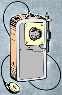
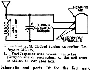
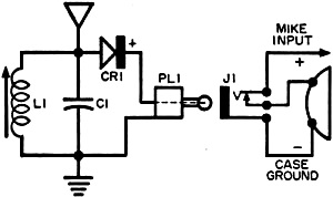
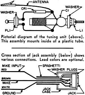
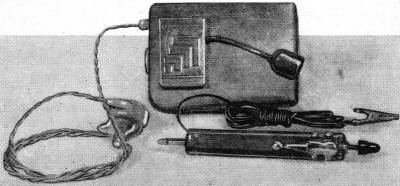
* Possible if dissimilar metallic junction was created, but could just be a much-promulgated myth. Radios Made from Hearing Aids With minor alterations and additions, you can make a radio from a hearing aid Radios that can be put in a pocket, worn on the wrist, or carried in a purse are extremely popular these days. You can go out and buy one of these pocket - or purse-size units, but you'll find it rather expensive. Besides, who wants to buy something that you can make? Here are two versions of a midget radio built around a hearing aid. You don't have to be hard of hearing to build these devices, but you will need a hearing aid in good working order. Perhaps you can pick up a used model for a reasonable price at your local hearing-aid dealer. In both cases, the hearing-aid is used as an audio amplifier and is preceded by a simple tuned circuit to select various broadcast stations. Range will depend on the power of nearby stations, and on the length of antenna employed. In metropolitan areas, you will probably be able to get quite a selection of stations without using any antenna at all. For other places - or inside steel-reinforced buildings - a wire three or four feet long will help. In each of the units described, the major work is mechanical rather than electrical, so you have plenty of leeway to use your own ingenuity. Different hearing aids will present different problems - the basic suggestions included here should enable you to convert practically any of the hearing aids now on the market to a suitable receiver. Unit One By Gary Edson The first unit involves the conversion of an Acousticon hearing aid. The tuned circuit consists of a Vari-loopstick with midget tuning capacitor such as the Lafayette part No. MS-215 connected in parallel with it. This capacitor is mounted in the space usually occupied by the microphone grille, which is removed; to fill in the extra space between the edges of the capacitor and the edges of the hole in the case, solder in a piece of sheet metal previously cut to shape. For other models, you can easily design a suitable mounting system. Cut off the threaded sleeve on the capacitor unless it is used for mounting purposes, and shorten the shaft so the tuning knob will not stick out too much. C1 - 10-365 μμfd. midget tuning capacitor (Lafayette MS-215) Schematic and parts list for the first unit. C1 - 330·μμfd. subminiature ceramic capacitor Schematic diagram and parts list for the second conversion described in text. Mount the loopstick by means of an L-shaped bracket bolted to the side of the hearing-aid case. Mount a binding post for an antenna, or merely solder a wire in place after you have determined the proper length. Connect the parallel coil and capacitor combination to the microphone terminals as shown in the schematic. You will probably note that no detector is employed - detection of the radio signal takes place in the grid circuit of the first audio stage. Volume and tone controls on the hearing aid are undisturbed; they can be used to control sound coming from the earphone. Adjust the coil slug for best performance over the whole band. A more compact receiver may be devised by using a coil from a 456-kc. i.f. transformer. The coil can be mounted inside the hearing-aid enclosure (without the i.f. can, of course) but performance will be inferior to that provided by the loopstick. An external antenna is a "must" with this scheme. Unit-Two By F. E. Bassett The second conversion is somewhat more involved mechanically, but has the advantage that you can unplug the tuned circuit and use the hearing aid for what it was originally intended - a hearing aid. Proper switching for this purpose is accomplished in the plug and jack arrangement, as shown in the schematic diagram. A glance at the photos and diagrams will give you a general idea of the jack and plug assembly. The tuned circuit components, L1 and C1, and the rectifier CR1 are all mounted inside a plastic tube about 3" long, having an inside diameter of 1/2". Suitable plugs and washers for the assembly are cut from a sheet of 1/8"-thick Lucite. To reduce the size of the coil, remove the solder lugs. Then carefully slit and remove the cardboard tube supporting the lugs. Pry open the adjusting screw mounting slightly so that the screw turns freely. This screw, with a suitable tuning knob made from the cap on a can of lighter fluid or other suitable device, is used for tuning the receiver. Mount and solder the tuner components as shown in the pictorial diagram, being careful not to overheat the rectifier. Cut washers for the plug end and for the snap-in end of the coil, slip the whole assembly inside the plastic tube, and glue the washers firmly in place with plastic cement or acetate liquid. Be sure to bring the antenna lead outside the case before final assembly. Mount a pen clip as shown below.
Pictorial diagram of the tuning unit. This assembly mounts inside of a plastic tube. Cross section of jack assembly (below) shows various connections. Lead colors are optional. Now wire up the jack as shown in the cross-sectional view, cut suitable washers from the Lucite sheet, and assemble inside a 5/8" length of plastic tubing - gluing the washers firmly in place. It is a good idea to use color-coded leads to make certain that you wire the plug to the hearing aid correctly. Remove the hearing aid assembly from its case. Unsolder the microphone input lead, and connect the three leads from the plug as shown in the cross section, and in the schematic. Protect these three leads with spaghetti tubing. Re-install assembly in case. With the tuner unplugged, the hearing aid should operate normally, Plug in the tuner, and clip the antenna lead to a metal lamp shade, phone finger stop, or outside antenna. Then turn up the volume, and hunt for stations by turning the coil adjusting screw. You should receive several stations with good volume and clarity. By eliminating the 330-μμfd. capacitor across the coil, the author was able to tune in a number of ham stations. Try experimenting with different capacitors to see how many short-wave stations you can find.
Happy listening!
Posted January 5, 2022 |
|

