Radio Control Installations
|
|
Anyone who has been in aeromodeling for more than a decade or so is familiar with the name William (Bill) Winter. Bill has been in the model airplane realm for longer than a lot of us have been alive and is one of the true pioneers of the sport. He has served as editor for a couple aircraft modeling magazines, and has written countless articles both for the magazines he edited and for other special interest magazines. When Popular Electronics came on the scene in the mid 1950s, Bill was editor of Model Airplane News. Radio control was beginning to mature from its infant state when only hobbyists with an intimate knowledge of electronics were able to participate. Oliver Read, editor of Popular Electronics, tapped Bill's ample knowledge and skill to craft quite a few articles for his own magazine. This one, Radio Control Installations, appeared in the February 1955 issue. As always when reading this type of vintage material, it is amazing how much innovation has occurred between then and today in the fields of electronics, materials, and construction techniques. Radio Control Installations 
by William Winter, Editor, "Model Airplane News" One of the oddities of the radio control hobby is the persistent underestimation, even by some manufacturers, of the problems of installing the airborne equipment. Most directions stop with a wiring diagram and the "dope" on tuning. It is no wonder then that the beginner's first R/C installation is a rat's nest of wires, or that the radioman's first model often is torn up by loose batteries and catapulting equipment on the first really hard landing. A shipshape installation is accessible, removable, facilitates proper functioning of the radio, protects the equipment, and, just as important, protects the airplane from the equipment in a crack-up. If these requirements are not met, the best radio in the world is rendered unreliable.
Let's take the requirements in the order given. First is accessibility. This, like Sergeant Friday, covers a lot of territory. Just because the frequency trimmer can be reached with a tuning wand doesn't mean that the receiver is accessible. A slug tuner which requires tightening of a lock nut so that vibration will not cause detuning, isn't accessible when the lock nut is under the receiver chassis! Or, you may want to reach the relay to clean a contact, or to adjust spring tension, or reset a contact. Battery voltages often must be read on the field, or batteries may have to be replaced, or the escapement or servo checked. Anything that requires observation or adjustment should be readily accessible. Equipment should be removable. Maintenance alone requires that all principal parts of the radio system be removable, that is, battery packs, receiver, and actuator. Exhaust smoke from the engine and dust on the field penetrate cabins, eventually causing leakages of capacitors, etc. It certainly is worthwhile to keep the receiver chassis clean. Soldered joints need regular inspection - components may have been pushed out of place, perhaps to the point of shorting out. Tubes may be loose, a burr might have developed on the revolving arm of the escapement, or the armature of a servo motor may require cleaning. The radio model is, after all, a real aircraft and, like a real aircraft, requires periodic checks. It is not uncommon for an active hobbyist to log a hundred or more flights a year. If the equipment is not inspected regularly, the model will become a casualty before that many flights can be racked up.
The stationary wiring can be constricted into a very small area by a compact arrangement of the permanently installed fixtures. By using miniature socket-type plugs, the receiver can be provided with a plug-in cable, and the battery pack with another. Either or both can be removed by slipping out the plug. Standardize your receiver cable connections to make receivers interchangeable between ships. One big advantage of this practice is that friends can cooperate by sharing receivers when necessary, provided the hook-ups are standard. On the five-pin plug the following connections are suggested: pin 1, "A+"; pin 2, "B+"; pin 3, common minus; pins 4 and 5, relay. Damping of vibration is accomplished by a variety of shock mounting systems, the two most common ones being a rubber band suspension of the receiver in a horizontal position, or the placement of the receiver upon a block of foam rubber, either vertically or horizontally. If vertically mounted, the receiver has an infinitely greater immunity to crack-up damage. Indeed, it is possible to destroy the airplane without detuning the receiver or even knocking the relay out of adjustment, when vertical mounting is used. Heavier and larger receivers sometimes rest upon two blocks of sponge, one at either end, or at either side, as the case may be. The rubber is faced with 1/16-inch thick plywood (using rubber cement) and the chassis ends or mounting lugs are attached to the plywood with small wood screws.
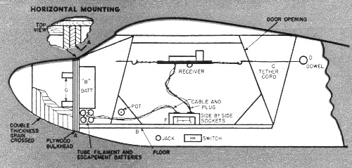
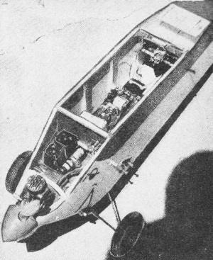
Example of battery installation in the belly of an airplane under the hardwood floor. The forward box contains a hearing-aid "B" battery, the rear compartment contains the batteries for the receiver filaments (1 1/2 volts) and the escapement requiring 3 volts. Good shock absorption is essential to good relay operation. The writer has seen cases where a 10,000-ohm sensitive relay considered shock proof would not pull in when mounted firmly on wood with a powerful engine shaking the airplane. Contact pressures may not be sufficient to hold a rudder in one position as the plane shudders out of a dive. Probably the manufacturers themselves don't know what happens to a relay armature during repeated signaling in the presence of a severe harmonic vibration, as only modelers seem to create it. If a good installation is able to employ the means of damping vibration to provide crash protection as well, you are ahead of the game.
Horizontally-mounted receivers which depend on rubber-bands from the four corners of the chassis may, on a short stop, penetrate a ply bulkhead with well imagined results to electronic equipment. A tether cord attached to the chassis and anchored behind the chassis to some strong point, prevents the receiver from traveling too far, although the back travel, like recoil of a gun, should be similarly damped for safety. Even though the horizontal mounting may hold in a crash, it is likely that the Sigma 4F-type relay will be deformed. Tubes will pop out, and everything that isn't tied down, like chokes, quench coils, and capacitors, will move out of position. Escapements and push rods take special handling to prevent crash damage. Escapements that simply are cemented against a balsa partition will tumble into the cabin when the plane bangs onto its nose. A pushrod may take off like a javelin, pulling loose the linkage assembly and the rudder.
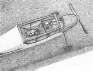
One method for mounting a receiver horizontally is shown here. Batteries and the socket for receiver cable are well forward.
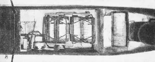
R/C model plane with the receiver mounted horizontally. The batteries are in the nose, mounted on a piece of plywood and inserted through the floor for easy accessibility.
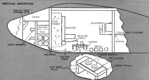
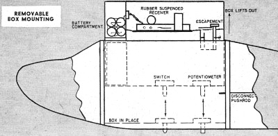
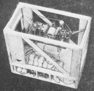
Removable box containing batteries, receiver, and actuator. This allows for easy removal from a plane and interchange between planes. The receiver is suspended by rubber bands (two light bands to each corner stretched to about one-third their limit). C is a tether cord attached to the rear wing hold-down dowel, D. F is a small chassis mounting two sockets, one to accept the battery cable lead, the other the receiver cable. Note the structural cross members, G, that reinforce bulkhead A. The section forward of this reinforcement is double skinned on each side, with the inner, thicker skin-3/16 or 1/4-inch thick sheet balsa, butting against bulkhead A. A popular mounting method is to have both receiver and batteries vertical. This provides excellent accessibility to the radio from the open top of the cabin, and to the battery pack from the removable top of the nose section. A is a 1/4-inch sheet-balsa bulkhead; B is either a 1/8-inch plywood or a 1/4-inch sheet-balsa bulkhead, whose grain runs across ship. Note that the impact of the batteries is against this bulk-head; that of the receiver, partly snubbed by foam rubber, is transmitted through A. The impact of the snug fitting batteries is transmitted to the key bulkhead B. Switches, potentiometer, and jack line up as before, well out of the way should the receiver swing from side to side. C is a foam rubber block, against which the receiver is anchored by small rubber bands. The tension of the bands is just enough to prevent the receiver from hanging loosely or swinging back and forth on landing. The battery cable D comes through bulk-head A, and plugs into a socket on chassis E. The receiver cable plugs into a similar socket. Note that the escapement is fully accessible. The beauty of the torque rod linkage to the rudder is that the linkage cannot damage the escapement in a crack-up, whereas the pushrod type transmits a blow to the escapement assembly. Pushrods and bellcranks also put a dead weight on the escapement, which can be a handicap when the nose is down. Pushrods usually require heavier rubber drive for safety and this in turn makes escapement and per-formance more critical. A variation of the vertical-type mounting is also shown. Here, a plywood floor A extends between bulkheads C and D. Observe that the floor continues forward of bulkhead B, so that the battery weight can be carried far enough toward the nose for correct balancing. Battery boxes bolt directly to the floor, and are accessible by means of a large bottom hatch. The Acme Products Company makes sturdy battery boxes for all popular battery combinations including hearing aid "B" batteries. If desired, a large "B" battery may be dropped into place between bulkheads B and D, with D then requiring the usual forward structural support. Escapements, switches, etc., are mounted as before. The large plywood floor is ideal for anchoring the heavier motor-driven servo-type actuators. Still another arrangement having very special advantages is the removable box method. This box contains the batteries, receiver, and even the servo or escapement. By detaching the linkage from the actuator, the box can be lifted from the plane without disconnecting a wire. Moreover, it can be dropped into another plane. It is unnecessary to have an actuator in every plane with this set-up. The batteries are packed in a forward compartment in the box; the actuator is mounted at the rear, but in such a manner that it does not snag the adjacent bulkhead when the box is lifted out. Switches, potentiometer, jack, etc., have to be on the bottom of the box, and are reached through holes in the bottom of the ship when the box is in place. In fact, the toggle switch handle extends from the bottom. Usually more confined than a wide open cabin, the box requires that some receivers be beam mounted, that is, placed upon two blocks of foam rubber at either end, or along the sides.
It would be well to draw upon these comments in sketching in any installation upon the plan that comes with your airplane kit - before cementing a piece of wood. Few kits detail installations, merely saying, put the batteries here, etc. Nor are they always wise in the location of some items such as an escapement. The average modeler is a great individualist, especially in radio control. So don't be afraid to "gild the lily." END
Posted November 25, 2022 |
|