Oscilloscope Traces: Radio Frequency Measurements
|
|
"Whenever some science fiction movie or TV show is intended to appear 'ultra-scientific,' or when a sponsor wants to clinch his sales pitch with some phony-technical display, chances are that an oscilloscope will be shown with a modulated wave pattern jumping around on the screen." Funny that this was going on back in 1957 when this article appeared in Popular Electronics magazine, and that it still occurs today. How many modern sci-fi movies or techie action movies have you seen that still show Lissajous patterns squirming around on oscilloscope screens? The only difference is today's hoaxes have rectangular displays whereas the old ones used round displays. Even though this article is over 50 years old, it still has some good pointers for newbie o-scope users. I'm guessing there are even a few veterans out there who have never actually driven the x- or z-axes of a scope themselves and seen what it does to the display. Maybe now's a good time to give it a whirl. Last month's article featured square waves. Oscilloscope Traces: RF Measurements
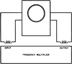
By Howard Burgess Whenever some science fiction movie or TV show is intended to appear "ultra-scientific," or when a sponsor wants to clinch his sales pitch with some phony-technical display, chances are that an oscilloscope will be shown with a modulated wave pattern jumping around on the screen. Such 'scope traces are, as it were, the popular image of scientific work. Checking the carrier frequency of a portable transmitter by the techniques described here will assure its proper functioning when it is taken into the field. Perhaps this particular trace has gained its popularity because it is so useful. It can be immensely valuable to anyone working with a modulated carrier. The carrier need not be one of a high power transmitter. It can originate from a wireless record player, a serviceman's signal traces can be obtained to well over one hundred megacycles. One use of the oscilloscope which generally requires this type of connection is the checking of frequency multipliers in transmitters. Many of the modern transmitters, both amateur and commercial, have one or more frequency multiplier stages following the crystal oscillator. If the output of the transmitter is to be on the correct frequency, each multiplier stage must increase the frequency by the desired number of times.
Fig. 1 - The oscilloscope is coupled to the input and output of a frequency multiplier stage in order to check its operation.
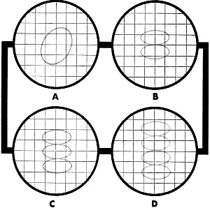
Fig. 2 - Scope patterns created by an r.f. stage in the hookup described in Fig. 1: (a) without frequency multiplication; (b) with frequency doubling; (c) with frequency tripling; (d) with frequency quadrupling. These patterns provide a quick check for frequency multiplier stages.
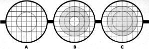
Fig. 3 - The circular patterns produced by r.f. on the 'scope screen are shown here for three different cases: (a) no modulation; (b) 50% modulation, and (c) 100% modulation of the carrier frequency.
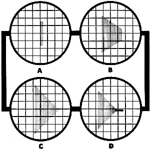
Fig. 4 - The trapezoidal pattern of r.f. as it appears with: (a) no modulation, (b) 50% modulation, (c) 100% modulation, and (d) overmodulation of the carrier frequency.
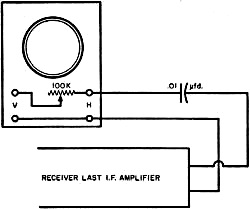
Fig. 5 - This simple circuit will usually produce a circular pattern at an r.f. frequency.
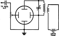
Fig. 6. Coupling the oscilloscope to produce a trapezoidal pattern on the screen. Counting Loops The output frequency of each stage can be checked with a good calibrated wavemeter if one is available. A double-check, and in many cases a better test, can be made with an oscilloscope. This method makes use of the Lissajous generator, a transmitter for opening garage doors or controlling models, or a ham transmitter. Direct Connection Very few amateurs own an oscilloscope with an internal amplifier able to pass the higher radio frequencies. However, in most cases this problem can be solved by feeding the r.f. signals directly to the deflection plates of the oscilloscope cathode-ray tube. Most oscilloscopes have these connections brought out to a small terminal board in the rear of the 'scope's cabinet. With the signal fed directly to the cathode-ray tube, pattern which is formed when two signals of different frequencies are applied to the vertical and horizontal plates of the tube. (See POPULAR ELECTRONICS, March, 1957, page 63.) If one set of deflection plates is coupled to the input of the multiplier stage under test and the other set of deflection plates is coupled to the output of the same stage (Fig. 1), the pattern formed will indicate the number of frequency multiplications taking place in the stage. The pattern most likely to be formed will be found among those shown in Fig. 2. They range from a multiplication factor of 1 (shown at A) to factor of 4 (at D). For those who are not familiar with this type of trace, examination of the figure will show that the multiplication factor is found by dividing the number of loops in the width of a pattern into the number of loops in its height. All of these patterns are one loop wide. In many cases the loops will not be as rounded and clear-cut as shown here; however, it is the number of loops and not the shape that matters in this case. Modulation Check Anyone that works with electronic equipment for any length of time sooner or later finds himself confronted with modulation problems. Even the experimenter who is not a licensed amateur would like to be able to check the modulation of stations that he hears. If precise checking isn't necessary, the simple test to be described will be adequate. The setup in Fig. 5 will usually do the job. The horizontal input to the 'scope is coupled to the plate of the last i.f. amplifier of the receiver through a small blocking capacitor. This added load will probably require a slight amount of retuning of the last i.f. transformer. The sweep generator in the 'scope must be turned off. Now connect the vertical input to the horizontal input through a 100,000-ohm potentiometer. Then, with a good strong signal tuned in on the receiver, adjust the vertical and horizontal gain controls of the 'scope and the variable resistor until a circle is produced on the screen. Circle Check Pattern. If the signal is not being modulated, the circle will be a sharp, well-defined pattern. As soon as modulation is applied to the carrier, the circle will alternately expand and contract to form a pattern similar to a doughnut. As the percentage of modulation is increased, the hole in the center will gradually close until it is completely closed at 100% modulation. If more than 100% modulation is present, a bright dot will form in the middle. The circle should move out the same distance that it moves in toward the center. Caution: Before alienating your transmitting friends by criticizing the signal they send out, make sure that the receiver you used for this test is in good condition. A properly modulated wave, upon passing through a poorly adjusted receiver, can appear either over-modulated or undermodulated. This system can also be used to check the output of signal generators which are operating on frequencies too high to be fed directly into the oscilloscope. Phono oscillators and similar gadgets can be checked for percentage of modulation in the same manner. The oscillator is tuned in on the broadcast receiver and the 'scope connected to the i.f. system of the receiver as outlined above. Trapezoid Check Pattern. Another modulation pattern which is formed in a manner similar to the circular trace is that of the trapezoidal figure. This type of measurement requires a direct power take-off from the transmitter tank and a sample of the audio used to modulate the transmitter. Because of this, it is not suitable for measuring the modulation of distant stations. The circular pattern serves that purpose. However, for continuous monitoring of a transmitter, the trapezoidal pattern is the simplest to obtain since it requires no amplifier or sweep circuits. Connections are made directly to the deflection plates of the cathode-ray tube of the oscilloscope as shown in Fig. 6. When the transmitter is not modulated, the .f. carrier will produce only a vertical line. When modulation is applied, it furnishes the sweep to form a triangle as in A of Fig. 4. If transmitter is modulated less than 100%, the triangle will not be filled out, as at B. Too much modulation will form a pinched-off pattern, as at C, with a bright trailing line. If the sloping sides of the triangle are curved rather than straight, the transmitter under test is distorting due to nonlinear operation. General Hints There are many other r.f. measurements that can be made with the oscilloscope which may be discussed in future articles. Whenever the 'scope is used for r.f., it is a good idea to keep leads short, with as little shielding as possible. And don't jump at conclusions. You will see a good many "queer" traces during your first investigations but, with growing experience in interpretation, important clues about the condition of your radio-frequency equipment will be clearly revealed to you. You will find that familiarity with radio-frequency traces will come in handy on many occasions. Wherever signals are actually sent out "on the air," it is necessary to check r.f. stages both at the transmitter and at the receiver, as well as to monitor the degree of modulation wherever the signal itself is more complex than simple c.w.
Posted November 18, 2022 |
|
 Wherever signals go "on the air" these tests
will tell you their nature
Wherever signals go "on the air" these tests
will tell you their nature