The NASA 136 Satellite Receiver Converter
|
|
The NASA 136
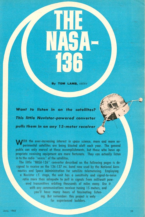
Want to listen in on the satellites? This little Nuvistor-powered converter pulls then in on any 15-meter receiver With the ever-increasing interest in space science, more and more experimental satellites are being blasted aloft each year. The general public can only marvel at these accomplishments, but those who have appropriate receiving equipment are more fortunate. They can actually listen in to the radio "voices" of the satellites. The little "NASA-136" converter described on the following pages is designed to receive on the 136-137 mc. band now used by the National Aeronautics and Space Administration for satellite telemetering. Employing a Nuvistor r.f. stage, the unit has a sensitivity and signal-to-noise ratio more than adequate to pull in signals from milliwatt powered transmitters orbiting thousands of miles away. Use it with any communications receiver tuning 15 meters, and you'll have many hours of fascinating listening. But remember: this project is only for experienced builders.
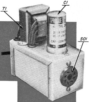
The completed converter and power supply chassis plug together to make one efficient, integrated unit.
Photograph of power supply's exterior.
Pictorial diagram of power supply interior shows all essential construction details. DETAIL A
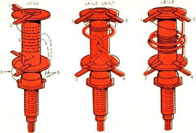
Drawings of the converter's major coils are shown here. Coil L1/L2 is wound exactly as illustrated (L2 is solid winding; L1 is dotted 2·piece winding). In coils L4/L5, L6/L7, and L8/L9, make L5, L6, and L9 (the heavy windings) as shown but refer to parts list for exact number of turns on L4, L7, and L8 (the fine windings). Numbers on the coil terminals are keyed to corresponding numbers on the schematic diagram.
Top view of converter. For exact parts placement, see Detail "B." DETAIL B
Location of components on top of converter chassis is critical, and the dimensions given in this illustration should be closely followed. DETAIL C
Side and top views of shield and V1 socket show how shield is bent, soldered to the socket. Components C11 and R1, which have been moved aside for a better view, should actually be positioned flat against shield.
Crossed leads running between L6/L7 and L4/L5 in converter chassis (below) are shown separated for convenience; they should be twisted together, routed in front of C3.
Parts placement shown in this photograph of the converter's interior, and in the pictorial diagram on the previous page, should be carefully studied and duplicated quite closely.
Track these satellites with the NASA-136.
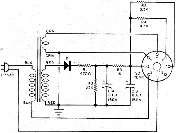
Schematic diagram of the power supply, which utilizes a simple half-wave diode rectifier. Parts List for Power SupplyC1a/C1b-20/20 µƒ., 150-volt electrolytic capacitor (Sprague TVL-2415 or equivalent) D1-65-ma., 130-volt (r.m.s.) selenium rectifier (Sarkes Tarzian Type 50 or equivalent) R1-470-ohm, 1-watt resistor R2-33,000-ohm 1-watt resistor R3-1000-ohm, 1/2-watt resistor R4-4700-ohm, 1-aatt resistor R5-3300-ohm, 1-watt resistor SO1-Octal socket (Amphenol 77MIP8 or equivalent) T1-Power transformer; primary, 117 volts; secondaries, 125 volts at 15 ma., 6.3 volts at 0.6 amp. (Stancor PS-8415 or equivalent) 1-4" x 2 1/4" x 2 1/4" aluminum utility box (Bud CU-3003-A or equivalent) Misc.-Terminal strip, grommets, line cord and plug, hardware, solder, etc.
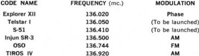
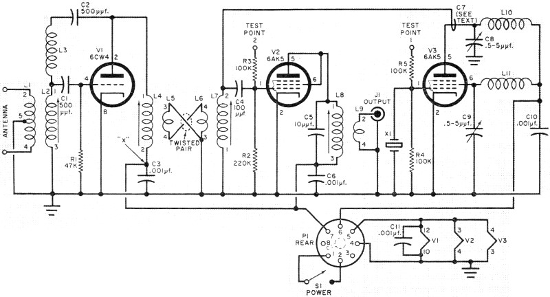
About the Circuit The 136- to 137-mc. signal from the satellite passes from the antenna to triode V1 (a 6CW4 Nuvistor), which is connected as a neutralized r.f. stage. From V1, the amplified signal is coupled to the control grid of V2, a triode-connected 6AK5 which serves as a mixer. The screen grid of crystal oscillator V3, another 6AK5, is tuned (by coil L11 and capacitor C9) to the 38 2/3-mc. fundamental frequency of crystal X1. Coil L10 and capacitor C8 tune the plate circuit of the tube to 116 mc., the third harmonic of the crystal frequency. This 116-mc. signal, like the 136- to 137 -mc. signal from V1, is injected into the control grid of mixer V2. In V2, a third signal is produced whose frequency is the difference between those of the first two. The third signal, which ranges in frequency from 20 to 21 me. (depending on the frequency of the signal from V1), appears across output jack J1. Power for the converter is furnished by a separate supply, and an octal output socket (SO1) on the supply chassis mates with a matching input plug (P1) on the chassis of the converter. Transformer T1 provides heater power and a source of line-isolated plate voltage. A single selenium diode (D1) is connected as a half-wave rectifier and its output passes through a pi-network filter. Note that, in case you want to use the power supply for other purposes, its full high-voltage output is available at pin 3 of SO1. No connection is made to the corresponding pin of converter power-input plug P1. Building the NASA-136. Start construction by putting together the power supply unit, which is housed in a 4" x 2 1/4" x 2 1/4" aluminum utility box. Generally speaking, neither the parts placement nor the wiring is at all critical Be sure, however, to mount output socket SO1 in the exact center of one of the box ends and to position the holes for the socket mounting screws so that the alignment key faces the bottom of the box. It's necessary to take this care in the positioning of SO1 because the socket must mate with P1, which is similarly placed on the converter chassis. When the power supply is completely wired up, temporarily jumper the remote-power-switch terminals (1 and 2) of SO1 and plug in the line cord. Use a multimeter to check for filament voltage (about 6.3 volts a.c.) between terminals 4 and 5 of the socket, and for plate voltage between terminal 4 and terminals 3, 6, and 7, respectively. The latter three readings should all be roughly the same (about 150 volts d.c.) since there is almost no load on the supply and, consequently, no, appreciable voltage drop across resistors R4 or R5. If the supply passes these tests, disconnect it from the line, install the cover, and temporarily set the unit aside. With the power supply taken care of, turn your attention to the construction of the converter itself. A logical first step is to wind the coils (L1-L11), specifications for which are given in the Parts List for the converter. Three of the coils (L3, L10, and L11) are wound on resistors. The leads of each of these coils are cut short and soldered across the resistor leads at points not far from where the latter enter the body of the resistor (be sure to carry out the soldering as quickly as possible to avoid heat damage). The resistor leads will then be used to wire the coils into the circuit. Coils L1/L2, L4/L5, L6/L7, and L8/L9 are wound on commercial slug-tuned forms. Diagrams of these coils (Detail "A") are given to supplement the information in the Parts List and should be followed as closely as possible. The forms for L1/L2, L4/L5, and L6/L7 are all of the same type. But the form used for L8/L9, though almost identical in appearance with the first three, is different. Be careful not to get them confused. The converter is housed in a 5" x 2 1/4" x 2 1.4" aluminum utility box. All of the parts, except power switch S1 and plug P1, are mounted on the top of the box. Parts placement is critical, and the dimensions given in Detail "B" should be closely adhered to. Plug P1 and switch S1 are mounted on the ends of the box. Center P1 and position its alignment key to match that of SO1 on the power supply chassis. A retaining-ring-mounted plug has been specified rather than a screw-mounted type so that P1 can be twisted, if necessary, to make it line up exactly with SO1. Switch S1 should be mounted slightly below center to insure enough clearance between it and the antenna terminal lugs. When all the mounting holes have been drilled, install the Nuvistor (V1) socket. This socket has two slots (one wider than the other) to accommodate the alignment keys on the base of the Nuvistor. Be sure to place the socket so that the wider slot is positioned as shown in Detail "B." The copper shield, which is formed and bent as shown in Detail "C," is placed over the Nuvistor socket and soldered to pins 8 and 10 (refer to Detail "C" and the pictorial diagram). Before mounting any other parts, make all the necessary connections to the Nuvistor socket. Then, as you proceed with the parts installation and wiring, be sure not to block component terminals before you have a chance to solder to them. Try to orient all components exactly as shown in the pictorial diagram and photos, and note the positioning of the V2 and V3 sockets as shown in Detail "B." A few points in the construction need special comment. First, capacitor C7 is nothing but a turn of insulated hook-up wire wrapped around the body of capacitor C8. Next, resistors R3 and R5 have nothing to do with the actual functioning of the circuit. They serve only to isolate the grids of V2 and V3, respectively, for test purposes. One end of each of these resistors is soldered to the appropriate grid; the other end, cut very short, is left free. Finally, do not connect the lead from pin 7 of P1 to the junction of capacitor C3 and coil L4 (point "X" in the schematic diagram). It must be left off temporarily in order to disable the r.f. stage during the initial steps in the adjustment procedure. Adjustment Besides your receiver (which should be equipped with an S-meter), you'll need two test instruments to carry out the adjustment: a d.c. meter with a range of approximately 0-100 microamperes (or a VTVM with a range of about 0-3 volts), and a signal generator which can be set at 136.5 mc. If the latter is unobtainable, a 2-meter ham transmitter tuned to 136.5 mc. will probably do the job. If you must use the transmitter, be sure that it radiates only the minimal signal required for adjustment purposes. Connect a dummy load across the antenna terminals and, if possible, leave the final off. If the final must be on, be sure that it draws minimum power. A signal radiated into space on this frequency is not only illegal, but it could easily interfere with vital government satellite telemetering. A word to the wise is sufficient. All adjustments may be made with the chassis covers removed. Begin by plugging in the power supply to the converter and to the line, inserting the crystal and tubes, and checking to see that the lead to L4 and C3 is disconnected at point "X." The negative lead of your test meter should be connected to test point 1 and the positive lead to ground. Turn on power switch S1 and, after the tubes have warmed up, adjust capacitor C9 for a maximum meter reading (this will probably occur somewhere near the minimum-capacity setting of C9) . Now change the negative meter lead to test point 2 and adjust capacitor C8 for maximum reading (once again, this will probably occur near the minimum-capacity setting). At this point, without changing the meter connection, capacitor C9 should be re-peaked. Typical final readings at test point 1 are -2 volts (read on a VTVM) or 32 µ.a. (read on a microammeter). At test point 2, the readings should be about -1 volt or 12 µ.a. If the reading at the latter test point is a little low, try making the loop of wire (C7) around capacitor C8 a bit tighter. This done, remove the meter and connect the antenna input of a receiver set at 20.5 mc. to the converter's output jack (J1); use a length of RG-58A/U coaxial cable. The receiver r.f. gain should be full on and the S-meter operating. Now adjust the slug of coil L8/L9 for maximum receiver noise. Couple the output of a signal generator (or transmitter) tuned to 136.5 mc. to the converter's antenna input. If you're using a coaxial output cable, connect it between one of the antenna terminals and ground. You should now hear the generator's signal at the 20.5-mc. receiver setting (or near it, if the receiver's calibration is slightly off). A fairly strong signal will be needed from the generator, since the converter's r.f. stage is disabled. With the signal tuned in, slowly adjust the spacing between the turns on neutralizing coil L3 for minimum S-meter reading. Use a plastic tool for this adjustment and be sure the receiver always stays tuned to the signal. Next, temporarily solder to place the lead left off of point "X," reduce the generator's output, and tune the slugs of coils L1/L2, L4/L5, L6/L7, and L8/L9 for maximum S-meter reading. Disconnect the lead from point "X" and readjust L3 for minimum reading. Then connect the lead again and readjust L1/L2, L4/L5, L6/L7, and L8/L9 for maximum readings. Repeat the procedure until there's no further change in the maximum and minimum readings. Finally, secure the turns of L3 with coil dope, permanently wire in the lead to point "X," and install the box covers. The converter is ready to go. It may be, however, that your receiver is a "ham bands only" model, and you would prefer to set the converter's output in the 21-22 mc. band. In this case, just substitute a 38 1/3-mc. crystal for the 38 2/3-mc. unit specified for X1 and follow the identical procedure outlined above. The only difference is that the receiver should be set at 21.5 mc., rather than at 20.5 mc., during the adjustments. Operation Wire the converter's output to your receiver's antenna input as described in the "Adjustment" section. Then connect a TV antenna, a 2-meter beam, or a 41"-long folded dipole to the converter's antenna input. If the lead-in is 300-ohm line, connect it across the two antenna terminals; if it's a coaxial cable, connect it between one antenna terminal and the chassis. Assuming that the receiver and crystal calibrations are accurate, the frequency of the received signal will be the receiver dial reading plus 116 mc. (115 mc. if you're using a 38 1/3-mc. crystal at X1). In other words, the 136-137 mc. satellite band will be tunable between either 20 and 21 mc., or 21 and 22 mc., depending on which crystal you use. While the three tuned circuits between the converter's antenna terminals and mixer grid tend to eliminate image responses, you may still pick up an image from a local FM station. Should this be the case, try installing a stub-type wave trap. If you have a coaxial lead-in, use an 18 1/2"-length of coax cable with one end open and the other connected, at the converter, in parallel with the lead-in. If you're using a 300-ohm lead-in, the stub is a 24"-length of 300-ohm line connected in the same way. As the payload weight of American satellites increases, so does the power output of the satellite transponders and beacon transmitters. More power and better antennas on the satellites enable SWL's to pick up these signals with greater ease. Satellite beacon transmitters were originally scheduled to operate around 108.0 mc., but because of the number of satellites the United States has launched, the band between 136.0 and 137.0 mc. has been set aside to give each satellite frequency room. All future satellites will carry a beacon transmitter or transponder operating in this frequency band, which is now used in countries outside the Iron Curtain for satellite tracking. Four satellites are transmitting as this is being written, and two more are likely to be launched and transmitting before this article is in print.
Schematic diagram of converter. Lead from pin 7 of P1 to point "X" is not connected at "X" until initial adjustments are finished (see text). Parts List for Converter C1, C2-500-µµƒ., 600-volt ceramic capacitor C3, C 10-0.001-µƒ., 500-volt, silver-mica button capacitor (Erie 370-FA-102K or equivalent) C4-100 µµƒ. 600-volt ceramic disc capacitors C5-10 µµƒ. 600-volt ceramic disc capacitors C6, C11-0.001 µƒ. 600-volt ceramic disc capacitors C7-1 turn of insulated wire around C8-see text C8, C9-0.5-5 µµƒ. tubular trimmer capacitor (Erie 532-A or equivalent) J1-RCA-type phono jack (Smitchcrajt 3501FP or equivalent) L1-5 turns of #24 enameled wire, center-tapped; bifilar wound with L2 L2-4 turns of #24 enameled wire, wound in center of a Cambridge Thermionic PLS6/2C4L/D form L3-25 turns of #30 enameled wire, close-wound on a 1-megohm, 1-watt resistor L4-4 1/4 turns of #24 enameled wire, close-wound near top of a Cambridge Thermionic PLS6/2C4L/D form L5-1 turn of insulated hookup wire wound on L4 L6-1 turn of insulated hookup wire wound on L7 L7-3 3/4, turns of #24 enameled wire, close-wound near top of a Cambridge Thermionic PLS6/2C4L/D form L8-23 turns of #32 enameled wire, close-wound in center of a CTC PLS6/2C4L/O coil form L9-2 turns of insulated hookup wire wound on L8 L10-11 turns of #24 enameled wire, close-wound on a 1-megohm, 1/2-watt resistor L11-37 turns of #32 enameled wire, close-wound on a 1-megohm, 1/2-watt resistor P1-Chassis-mounting octal plug (Amphenol 86-CP8 or equivalent) R1-47,000 ohms 1/2-watt resistors R2-220,000 ohms 1/2-watt resistors R3, R4, R5-100,000 ohms 1/2-watt resistors S1-S.p.s.t. toggle switch V1-6CW4 tube (RCA Nuvistor) V2, V3-6AK5 tube X1-38.66666-mc., 3rd-overtone crystal (International Crystal Type FA-5) 1-5" x 2 1/4" x 2 1/4" aluminum utility box (Bud CU-3004-A or equivalent) 1-Nuvistor socket (Cinch-Jones Type 5NS or equivalent) 2-7-pin miniature tube sockets, wafer-type 1-Socket for X1 (International Crystal 150-109 or equivalent) Misc.-Scrap copper for tube shield, wire, 2-1ug terminal strip (screw type), length of coax cable, hardware, solder, etc.
Posted December 21, 2022 |
|