No Snow in June: Match Your TV Antenna to Receiver for Best Possible Picture
|
|
Few homeowners in the era of television antennas on the roof had any knowledge at all about how the antenna and twin lead transmission line system worked. Even those who were familiar with it only knew the basics like keeping the transmission line away from metallic objects and properly terminating the ends. I have seen photographs from servicemen of twin lead laying in aluminum guttering and along the top of chain link fence rail, and amazingly, the TV set still received a fairly good picture. That must have been in areas with exceptionally strong signals. This article in a 1970 issue of Popular Electronics magazine described a method for optimizing the antenna and transmission line in terms of impedance matching and using very low loss open ladder line to optimize signal strength to the receiver. It is exactly the subject (received signal strength) I recently lamented about being often ignored when discussing aspects of antennas and transmission lines. No Snow in June: Match Your TV Antenna to Receiver for Best Possible Picture
Good TV reception is not obtained by accident; it is carefully sought for and designed into your antenna system. You can get the best antenna and lead-in cable money can buy, but if the antenna is not impedance-matched to the cable and/or the cable is not matched to the TV receiver, you might just as well be using outdated "rabbit ears." This is especially true for color TV reception - and not just in the "fringe" reception areas. Everything in your TV receiving system must be just perfect, and the only way you can make sure that it is is to do the job right - the first time. But do not think that you have to be a TV antenna / transmission line expert to set up a receiving system. With the help of the information provided in this article, you can set up the best possible antenna system. The Loss Factor. Nothing is perfect. No matter whether it is an automobile engine or an electronic circuit, every system suffers from some type of loss which reduces its efficiency. While you cannot completely eliminate receiving system losses (known as signal attenuation), you can limit them to an acceptable level.
Fig. 1 - Transformers are cut to specific lengths for individual channels or for multichannel band. To demonstrate how loss becomes a critical design factor, consider a 300-ohm folded dipole antenna (tuned or cut to any TV channel) connected to a length of 300-ohm twin-lead cable. Very little loss would occur between the antenna and cable for the channel to which the antenna is tuned. But for all other channels in the TV band, the loss might be as high as 3-4 dB; and over the complete band, an average loss of 2 dB would be typical, enough to cancel the characteristic 2-dB gain of the folded dipole (favorably oriented) antenna. Now, consider a resonant 300-ohm folded dipole, reflector, and several director array (representative of most commercial TV receiving antennas). An estimated 2-dB loss would occur at the antenna/cable connection due to the lowering of the dipole's impedance. (The effect of placing a reflector and directors in close proximity to the folded dipole is to lower the 300-ohm characteristic impedance of the dipole to about 70-100 ohms). But since this antenna array provides 6-10 dB of gain, a 2-dB loss, severe in our first case, can usually be acceptable, particularly in good reception areas. For both cases cited above, the cable lead-in loss, assuming about 40' of twin-lead at VHF, amounts to between 0.6 and 1 dB. Hence, the total loss in antenna signal strength is 3 dB. This means that only 50% of the antenna signal power would be delivered to the TV receiver.
Fig. 2 - Insulator spacers support gradual tapers when matching 600-ohm open line to 300-ohm cable. Reducing the losses. The choice of improving the antenna-to-transmission line match basically involves inserting an impedance-matching transformer between antenna and line. The drawing in Fig. 1 illustrates the makeup of one type of transformer you can use. It is easy to fabricate and consists of two lengths of 300-ohm twin-lead cable. The decision of whether to fabricate your own transformer as opposed to buying one that is commercially made should depend on the end results. Tests made with both types show that at the 70-MHz frequency of channel 4, the commercial ferrite-core balun lowers the signal level by about 2 dB, while the quarter-wave, twin-lead homebrew transformer improves the signal level by 1.5 dB.
You may be wondering when and where it is advantageous to use these methods for improving signal transfer. As a general rule, they should be employed in "fringe" reception areas to improve weak TV channel reception. When making your own transformer or transformers, refer to the Table for the proper quarter-wave transformer lengths to use for each TV channel in the VHF spectrum. The lengths listed were computed assuming standard 300-ohm twin-lead cable with a phase factor of 0.84, which is typical for polyethylene-jacketed twin-lead.
Fig. 3 - Gradual taper matches 300·ohm twin-lead cable to 150-ohm impedance of Pyramidal Antenna. Now, take three practical examples to show how to improve TV reception. In the first example, suppose you have a good quality commercial antenna array and wish to improve reception on Channel 4 by inserting a transformer section between the antenna and a 300-ohm twin-lead line. Select the transformer length section from the Table; in this case, 36" is indicated. Cut two pieces of twin-lead cable to exactly 36" (plus about 1/2"extra at each end). Strip away 1/2" of insulation from each end of both cables. Then, connect the lengths of twin-lead in parallel with each other (see Fig. 1). Insert the transformer section between the antenna and twin-lead lead-in cable. This should yield an improvement of 1.5 dB in signal strength and a noticeable improvement in Channel 4 fringe-area reception. For our second example, suppose you use the same antenna and want the best possible reception. Rather than running 300-ohm twin-lead cable, try using lower loss 600-ohm open line. This can be done fairly easily by following the instructions detailed in Fig. 2. At both the antenna and TV receiver, the line must be tapered gradually to the 600-ohm spacing of the open line. When completed, the installation should yield about a 2-dB improvement in signal reception, slightly better than in the first example.
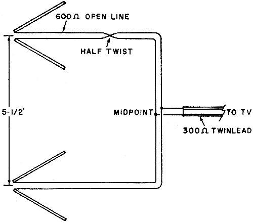
Fig. 4 - Open line matches two Pyramidal Antennas to 300-ohm cable. Note half twist in 600-ohm line. As a final example, assume you are planning to erect the Pyramidal TV/FM Antenna ("Build The 'Pyramidal' TV/FM Antenna," Popular Electronics, July 1969). This antenna's impedance is about 150 ohms, which means that 300-ohm twin-lead cable is reasonably ideal to use. However, for the ultimate match, you should insert a tapered section of line between the antenna connecting terminals and the 300-ohm twin-lead lead-in cable as shown in Fig. 3 to improve reception by about 0.5 dB. The added complication of tapering the line in the last example might not be justified, considering that this antenna has a nearly flat gain characteristic of 10 dB for all VHF TV channels. Finally, suppose that even 10 dB of gain is not enough to provide quality fringe-area reception. You could stack two Pyramidal antennas as shown in Fig. 4 to obtain 13 dB overall gain. Here, the individual antenna connecting point impedances can be tapered to 600 ohms and then paralleled, providing an ideal match to the 300-ohm twin-lead cable line to the receiver. In the illustration, the center-to-center spacing between the antennas is 5'. Of course, the antennas could just as easily be placed side by side to yield the same resultant gain; but erection on a single mast is usually easier to implement. Now that you have been apprised of good receiving system basics, you can start designing your own system. And with the warm weather here, what better time is there to tackle the job?
Posted March 5, 2024 |
|
 By George Monser