Inside the Power Amplifier, Part 1
|
|
There are still a lot of vintage vacuum tube-based power amplifiers in service. While this article from the July 1959 edition of Popular Electronics magazine focuses on an audio power amplifier, the principles apply at least into the lower RF frequencies used by amateur radio hobbyists and even commercial broadcast equipment. Fundaments of waveform analysis and amplifier operations are covered. Distortion due to nonlinear characteristics of active components is a prime concern for maintaining linearity at all frequencies and for making certain that harmonics and subharmonics are not being blasted into the ether. Dig the large size classroom demonstration model of the amplifier chassis. Those kinds of props were popular with both military and civilian schools. This is part of a many-month "Inside the..." series of articles written by Joseph Marshall. Inside the Power Amplifier  Part 1 Part 1
By Joseph Marshall In previous articles in this series we have discussed the functions performed by a hi-fi preamplifier. But when the preamp's job is done, what have we? Only a puny little signal that is rarely more than two volts, and more commonly in the neighborhood of one volt, and - most important of all - with no power behind it. If you feed this voltage to a speaker system, nothing will happen - no sound, no nothing. Clearly, we need another link in our hi-fi chain, a power amplifier. The purpose of the power amplifier is to take the weak signal from the preamp and amplify it until it is powerful enough to drive a loudspeaker system to the loudness level of a symphony orchestra. And it must do this without changing the signal. The first part of this task is not too tough; it is the second part that enables audio engineers to make a comfortable living. Disappearing Watts. The sound level of a symphony orchestra can be reproduced in the average living room with a power of about 0.5 acoustic watt. Unfortunately, however, loudspeakers are inefficient devices. It may take anywhere from 5 to 50 watts of audio power to drive some speakers to 0.5 acoustic watt, and as much as 100 audio watts to drive other speakers to the level liked by some audio fans. At one time, 10-watt amplifiers were thought to be the "ultimate" in power, but with the introduction of several speakers with unusually low efficiencies, amplifiers of higher power have become quite popular.
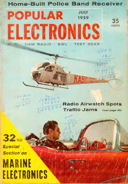
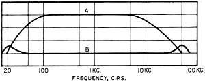
Fig. 1 - Frequency response curves of typical low-priced amplifier show that response at high and low frequencies suffers at high power output levels.
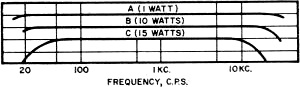
Fig. 2 - Negative feedback reduces distortion. In (A) original signal is undistorted, but after passing through amplifier, it appears as (B), with a "pip" on top. Portion of output is fed back to input of amplifier out of phase with original signal (C), and resultant input signal is shown in (D). "Pre-distorting" the input signal allows resultant output (E) to follow original input signal accurately.
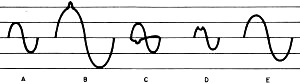
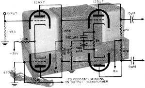
Typical feedback circuit; feedback path is from plate of second tube to cathode of first tube.
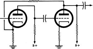
Fig. 3 - Curve A above shows response curve of amplifier with no negative feedback. If feedback is used in an amplifier which has an inadequate frequency response, amplifier may become unstable, as indicated by Curve B.
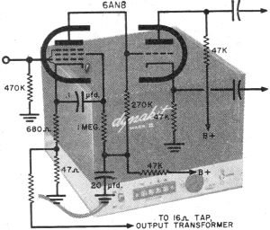
Fig. 4 - Dyna "Mark III" power amplifier features a pentode voltage amplifier direct-coupled to a triode split-load inverter. Both functions are handled by one tube, a 6AN8.
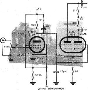
Fig. 5 - Mullard circuit as employed in the Eico HF-60 uses a pentode voltage amplifier direct-coupled to a cathode-coupled inverter.
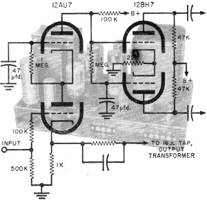
Fig. 6 - Grommes 250K utilizes a 12AU7 as cascode voltage amplifier followed by a 12BH7 cathode-coupled phase inverter.
Fig. 7 - Acro "Ultra-Linear"II" has a cathode-coupled inverter direct-coupled to push-pull triodes. This feature results in an "all push-pull" amplifier. Figure 1 shows the response curves of a typical low-priced amplifier at various power levels. Curve A is the response at a level of 1 watt, Curve B at 10 watts; and Curve G at the rated output of 15 watts. Note that the amplifier delivers 15 watts between about 60 and 10,000 cps, but it delivers less than 15 watts at 20 and 20,000 cps. Therefore, although this amplifier can be honestly rated by the manufacturer as a 15-watt job (at 1000 cps) , it does not function as a 15-watt amplifier at the extremes of the audio range. Negative Feedback. Although the maximum output of hi-fi amplifiers is usually rated at the point where the distortion reaches 2%, it is generally agreed that amplifier distortion should not exceed 0.5% at any point in the audio range. Negative feedback is the major distortion-reduction tool of the audio designer. The principle of negative feedback is shown in Fig. 2. In Fig. 2 (A) we have the original signal, pure and undistorted; but when it comes out of the amplifier as shown in Fig. 2(B), it has a peak or "pip" on it. Now suppose we take a portion of the output signal and apply it to the input tube of the amplifier in parallel with the input signal, but exactly out of phase with it. See Fig. 2(C). Because the signal we feed back is in reverse phase, it will subtract from the input signal and reduce its amplitude. Clearly, it will reduce the amplitude more at the point where the peak in the feedback signal appears, and, in fact, will put a dip at the exact point where the amplifier puts a peak. The resultant signal at the grid of the input tube is shown in Fig. 2(D). When this signal goes through the amplifier, the peaking. effect of the amplifier fills in the dip we have created, and the resulting output, shown in Fig. 2(E), although of lower amplitude than that of Fig. 2(B) , is almost as pure as the input signal. Thus, by "predistorting" the signal at the input, feedback compensates for the distortion of the amplifier. Although it's never possible to eliminate distortion entirely, if we use enough feedback we can come very close to it. For example, we can take an amplifier that delivers 15 watts with 2.5% distortion and, by adding 20 db of feedback, we can theoretically reduce the distortion to 0.25%. Design Considerations. Negative feedback is not miraculous. Like anything else, it has its limitations. The problem can be visualized by referring to Fig. 3. At Curve A we have the response of an amplifier without feedback. Note the slopes at the two ends of the curve. One of the hard facts of hi-fi life is that where there is a slope there is also a phase shift. As we apply feedback to the ranges represented by the two slopes, the phase of the feedback is no longer exactly 180° out of phase, but is either slightly greater or less than 180°. If we go far enough, or if the slope is steep enough, we come to a point where the feedback signal, rather than being out of phase, is actually in phase. When in-phase signals are fed back, we get a pair of peaks at the opposite ends of the audio spectrum, as indicated in Curve B. When such peaks are present, the amplifier is usually unstable and may be thrown into momentary or continuous oscillation at the frequencies where the peaks occur. We can avoid this by controlling the amount of feedback used in the circuit. Obviously, the flatter the response of the amplifier before feedback is applied, the more stable the amplifier will be when we apply feedback. Therefore, the audio designer starts by designing the best possible circuit without feedback. In fact, almost any genuine hi-fi amplifier is fiat at least over the audio range even without the feedback loop. Now we undertake the problem of keeping the amplifier's response fiat over a wide bandwidth. At the low end, a sloping response is the result of time constants in the circuit produced principally by the coupling capacitors between stages. The fewer the coupling capacitors, the fewer the time constants, and the less the slope. There are two ways to reduce the number of coupling capacitors: (1) by reducing the number of stages that have to be coupled; and (2) by direct coupling (no capacitors) between stages. Almost all modern power amplifiers employ a combination of these two methods. Excluding the output stage, the power amplifier usually has at least two stages: a phase inverter to convert the single-ended audio signal to push-pull (to feed the push-pull output stage); and a voltage amplifier stage. Most modern amplifiers employ a voltage amplifier directly coupled to the inverter (or vice versa) which is capacitor-coupled to the output stage. Thus, we have only one time constant to affect low frequency performance. Two major causes of a sloping high end response in the front end of the power amplifier are: (1) the grid-to-plate capacitance of the tubes which acts as a bypass around the tube at high frequencies; and (2) capacitance from tube elements and wiring to ground. Obviously, the fewer the stages, the fewer the bypass points; hence, reducing the number of stages to a minimum helps the high end as well as the bottom end. Problems of tube capacitances are minimized by using special miniature tubes designed for less capacitance than larger tubes and by using pentodes rather than triodes. Pentodes have very low capacitance and can provide response well above the audio range. As a result, a high proportion of modern amplifiers employ pentodes as voltage amplifiers. Phase Inverters. Almost all commercial amplifiers today use either the split-load or the cathode-coupled inverter. In the split-load inverter, the load is divided evenly between plate and cathode. The output at the cathode is always 180° opposite in phase and equal to that at the plate; therefore. we have the necessary push-pull signal needed to drive a push-pull stage. This inverter is simple and inexpensive. it has low distortion. and with carefully matched plate and cathode resistors. it is capable of well-balanced output. The split-load inverter, however, provides no signal gain. In the cathode-coupled inverter, a high-mu twin-triode is usually employed. The signal is fed to one triode which operates as a regular amplifier with a large cathode resistor. The other tube operates as a grounded-grid amplifier, obtaining its input from the cathode of the first tube. Outputs from the plates of the two triodes are 180° out of phase, and thus, again, we have the needed push-pull signal to drive the output stage. This inverter can be designed for considerable gain. Typical Circuits. A very successful circuit first used in the Dyna amplifiers is diagrammed in Fig. 4. Here we have a pentode as the input tube/voltage amplifier direct-coupled to a triode split-load inverter. Both the triode and the pentode are part of a single 6AN8 tube. The bandwidth of this circuit is very wide and has very small losses at both low and high frequencies. Given a good output transformer, it is no trick to obtain 20 or 30 db feedback with it. This circuit supplies the 30-55 volts of signal to drive the larger output tubes, such as the EL34, KT88, 6550, etc. In lower powered amplifiers, a triode is sometimes substituted for the pentode because the tubes (usually the EL84) used in these amplifiers need fewer volts of drive. A twin-triode is generally used; one half for the amplifier and the other half as the inverter. Another popular circuit is the so-called "Mullard" configuration shown in Fig. 5. Again we have a pentode voltage amplifier, direct-coupled to a twin-triode cathode-coupled (or long-tailed pair) inverter which is capacitor-coupled to the output stage. This circuit has more gain that the Dyna circuit, but losses at very high frequencies are slightly greater. Here, again, a triode is sometimes substituted for the pentode in lower powered amplifiers. The preceding circuits are used in probably 90% of the power amplifiers on the market, but there are a number of interesting variations. In Fig. 6 we have a circuit used by Grommes which employs a twin-triode as a cascade voltage amplifier. The cascade has most of the virtues of the pentode and, in addition, is perhaps a little more stable. The cascade voltage amplifier feeds a cathode-coupled inverter. In Fig. 7, in a circuit used by Acro, we have a cathode-coupled inverter at the input which is direct-coupled to a push-pull pair of triode amplifiers. This results in an amplifier that is push-pull from beginning to end. Feedback from a special winding on the output transformer is applied to the inverter grid, which is normally at a.c.-ground potential. Though each of these circuits has its own advantages and disadvantages, all are capable of producing superb performance. But overall design, not the design of any single circuit, determines the end quality of an amplifier. Next month we will consider the design of power output stages and the part it plays in the over-all circuitry of an amplifier.
Posted October 24, 2022 |
|