What Ground?
|
|
Establishing a good ground connection is more important than ever with all the vulnerable electronics devices connected to house wiring for the Internet of Things (IoT). The old saying of "Ground is ground the world around" is only true if you actually have a good path to that ground potential. This article discusses methods for determining whether or not you have a low resistance ground interface, and how to establish one if needed. However, that is only the below-grade part of the equation [ground rod(s) and possibly conduction-enhancing chemicals]. Installing a low resistance and equally important low inductance path above grade to the below grade component(s) is essential for maximum protection. Lightning is a transient phenomenon, so the di/dt part of the v(t) = L * di/dt equation governing voltage across an inductor indicates that the faster the current is changing, the greater the voltage will be. Since current flowing between two points is proportional to the difference of potential between them, a really sharp lightning bolt that manages to induce a current in the above grade environment will cause a large instantaneous potential to develop across a high inductance path to ground - equivalent to having a large series resistance - thereby hindering charge dissipation to ground. What Ground? A Ground is Not Always a Ground ...
Have you noticed that both your transmitter and receiver seem to operate better on a wet, rainy day than on a dry day? The transmitter seems to "get out" a little better, and the receiver seems a little "hotter" during these times. The question we are about to answer is why the weather should have an effect on both these pieces of electronic equipment. Of course you know that many types of electronic equipment, especially transmitter's and receivers, require the use of a good ground for maximum operational efficiency. But, just what is a good ground? Too many people take a ground for granted. You cannot just drive a copper rod into the soil and expect your grounding problems to be solved. By pure luck they may be, but chances are that your problem is only partially solved. To establish a good ground, you must have a low-resistance area completely surrounding the grounding rod. Actually, the resistance of a ground is determined by the resistance of the set-to-ground lead, the ground rod, the rod-to-soil contact, and the resistivity of the soil surrounding the rod. The resistance of the lead, ground rod, and rod-to-soil contact is insignificant when compared to the resistance of the soil surrounding the rod. Tests have shown that if the rod is free of paint or grease and the soil is packed tight around the rod, contact resistance is negligible.
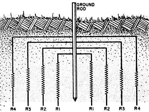
Fig. 1 - The soil around a ground rod can be considered as a concentric array of resistance, becoming smaller as the distance from the rod is increased.
Fig. 2 - When soil temperature is held at a constant 70°, its resistance increases as moisture decreases. The increase is rapid when moisture is below 20%.
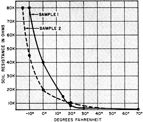
Fig. 3 - When soil moisture is held at a constant 22%, resistance increases with temperature reduction.
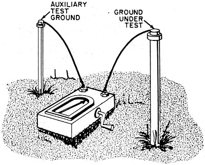
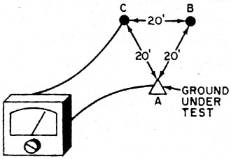
Fig. 4 - A megger can be used to determine the resistance of the ground rod under test, as shown above. To understand soil resistance, picture the ground rod as being surrounded by successive shells of uniform-resistance soil of equal thickness, such as shown in Fig. 1: The first shell, nearest the rod, will have the smallest cross section of soil at right angles to the current flowing out from the rod; so it will have the most resistance. The next shell will have a larger cross section and will have less resistance. As the shells get farther away from the rod, the cross section of each increases and resistance goes down until finally a point is reached where the addition of more shells adds nothing to the ground resistance. Tests have shown that this point is usually reached between 6 and 10 feet around the rod, This answers one question which is frequently asked - Why not use more than one ground rod? The answer is simple - any other rod driven within the 6 to 10 foot circle will do little to lower the resistance of the original ground. It must be driven outside this circle so it will act like resistors in parallel and lower resistance, Effect of Soil Composition. Tests show that the lowest resistance occurs in a soil made up of more or less refuse such as ashes, cinders, and brine waste. An average ground in this material measured 14 ohms. Clay, shale, adobe, gumbo, and loam soils came next with an average ground resistance of 24 ohms. Mixing these soils with sand, gravel, and ashes increased the resistance to 93 ohms. Finally, when only sand, gravel, or rock were present, with little or no soil, the resistance rose to 550 ohms. All these measurements were made on a cubic centimeter of soil with the temperature held constant at 70°F and moisture held at a constant 30%. Effect of Moisture. Another factor that has a great effect on soil resistance is moisture. When the moisture content of the soil falls below 20% the resistance goes up rapidly as can be seen in Fig. 2. For example, a given sample of soil with 10% moisture content has a resistance of 350,000 ohms per cm3. Increasing the moisture to 20% brings this resistance down to 10,000 ohms per cm3. If the moisture is increased to 35%, the resistance is cut to 5000 ohms per cm3. Moisture content of typical soil varies from about 16% during dry seasons to about 35% during wet seasons, averaging out at about 18%. This is why the resistance of a ground rod driven into the earth will often, more than double from a wet spring to a dry fall. Effect of Temperature. Another item that greatly affects the resistance of ground is temperature. A great change takes place especially when the ground freezes. The resistance of a soil sample with a stable moisture content rose from 200 ohms per cm3 to 500 ohms per cm3 as the temperature fell from 70° to 35°F. When it suddenly dropped to 20°, the resistance rose to 6000 ohms per cm3, and at 0° the resist-ance had gone up to 40,000 ohms per cm3. Fig. 3 shows the results of some tests. Where the ground freezes, it is especially important to be sure that the ground rod is long enough to reach about two feet below the frost line. This will usually put the rod into soil that has a reasonably permanent moisture level and temperature stability. The surface top soil is subject to wide variations in resistance with changing seasons. The greatest reduction in resistance is ordinarily encountered in going down the first 6 feet, but 8-foot rods have proven to reach permanent moisture. levels in 90% of the test cases. Rod Size. Thinking about the above-mentioned factors, one might surmise that the diameter of the rod might help in lowering the resistance. Test comparisons made between a one-half inch and a one-inch ground rod under controlled moisture, temperature, and soil conditions revealed that the one-inch rod with twice the diameter and four times the surface area decrease the resistance by only 4.5%. In general, the rod need only be large enough and strong enough to withstand driving into the ground without bending. Measuring the Ground. There are several methods of measuring ground resistance, and two will be explained. Using a megger is one method. It is probably the easiest and most accurate; If you don't know someone who has one, you can sometimes borrow one from your local power or telephone company. Probably the most popular megger is the old military PSM-2. To use the megger, you attach one lead to the ground to be measured and attach the other lead to an auxiliary ground rod which is driven into the ground some distance away (depending on the type of megger used). Then operate the megger to generate the voltage that causes the instrument to indicate the resistance of the ground path on the meter. Fig. 4 shows this method. Using an ohmmeter and two ground rods is another, although more cumbersome, method. Why two ground rods? Well, the ground that you are using now, whether it be a water pipe or an 8-foot ground rod driven into the earth, has an a.c. (caused by ground current) and a d.c. (caused by electrolytic action) component. Therefore, we need two more rods so we can take a series of readings and eliminate both components to get a true reading. Fig. 5 shows placement of the extra rods with respect to the ground under test. After driving the ground rods, label the rods "A", "B", and "C", with "A" being the actual ground rod you are going to use and want to measure. Take a resistance reading between "A" and "B" with the ohmmeter set on the low ohms range (usually in the 100 to 150 ohm range), then reverse the leads and take the reading again. Reversing the test leads nullifies the effect of the d.c. component.
Fig. 5 - When using an ohmmeter to determine ground resistance, two extra rods must be driven and compensation then made for stray a.c. and d.c. currents.
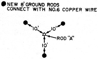
Fig. 6 - Ground resistance can be reduced by driving three more rods, then interconnecting all four rods.
Fig. 7 - Chemically treating soil can reduce ground resistance. However, the treatment must be renewed each year or so to maintain ohmic reduction. As an example of using this method, here are details of a typical test. Step 1. The "A" to "B" reading was 93 ohms, and the "B" to "A" reading was 67 ohms. Adding the two values and dividing by 2 produces an "A + B" reading of 80 ohms. Step 2. The "A" to "C" reading was 103 ohms and the "C" to "A" reading was 71 ohms. Adding the two values and dividing by 2 gives" A + C" reading of 87 ohms. Step 3. The "B" to "C" reading was 83 ohms, and the "C" to "B" reading was 113 ohms. Adding the two values and dividing by 2 produces a "B + C" reading of 98 ohms. Step 4. These values can now be substituted in the following equation: [(A + B) + (A + C) - (B + C)]/2 = value of A in ohms. Substitution of the values into the equation and working it out shows that the value of A is 34.5 ohms. For greater accuracy, the resistance of the auxiliary grounds should be near that of the one being measured and both should be at least 20 feet from each other and the ground rod under test. This is to prevent overlapping their effective resistance areas. When measured with a megger, the reading was 35.7 ohms so the accuracy of the ohmmeter method is good, although more involved and requiring more work. Lowering Ground Resistance. One might be thinking now, how do I go about lowering ground resistance if it is too high and, incidentally, what is "too high"? In most cities, the electrical code states that any electrode driven into the ground must read less than 25 ohms to ground. In the example previously given, note that the ground resistance value is too high (34.5 ohms.) Let's use it as an example to bring it down to 25 ohms or less. One method is to drive more ground rods as previously explained, since it would be like putting resistors in parallel, thus lowering the total resistance if all are connected together. This was done by placing three more 8-foot ground rods, ten feet from the original, and then connecting them all together as shown in Fig. 6. After doing this and then checking ground resistance, it was found that in a wet spring the resistance was about 18 ohms, and in a dry fall (or when the ground was frozen in the winter) resistance was about 22 to 23 ohms. Another method would be to drive the rod deeper into the ground. For instance, it has been found that a ground that measured 270 ohms at 8 feet measured only 10 ohms at 40 feet. However, if your ground is rocky, and more rods would not help a great deal, and the rods are very difficult to drive, one should consider treating the soil with chemicals. To do this, dig a circular trench about one-foot wide and one-foot deep having a 1 1/2 foot radius, as shown in Fig. 7. Fill this trench with copper-sulfate, magnesium-sulfite, or plain ordinary rock salt. Wet it down and cover with about three inches of soil or sand. This method works well with ground that has a high resistance, but the improvement decreases with time and should be renewed every year. If you "don't renew the treatment, the ground resistance will creep back up to its original high value. Also, the rod should be checked every three or so years as chemical action will eventually destroy it.
Posted August 9, 2018 |
|