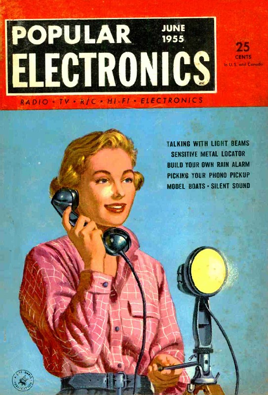
Geniac Problem Solving Computer
|
|
* Thanks to Mr. Wilson Roe, a former electronics repair shop and sales store owner on Tilghman Island, Maryland (from whence my mother's family hearkened), whom I later worked with as an electronic technician at Westinghouse Electronic Oceanic Division in Annapolis, Maryland (next to the Chesapeake Bay Bridge), who generously gifted his Timex Sinclair 1000 computer to me sometime around 1985. Geniac
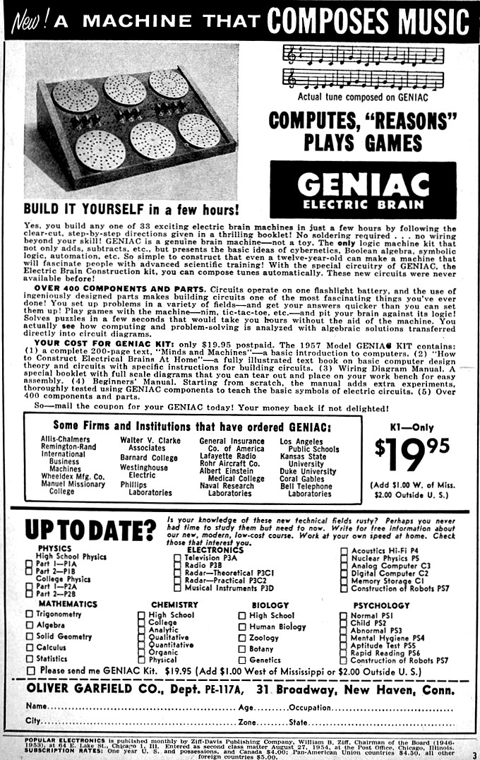
Interesting kit builds circuits that solve problems and play games /p> Cynthia Scott (Mrs.) and Marlene Saunders (Mrs.) - "two jealous wives" - eye each other with suspicion while awaiting Geniac signal. Circuit warns wife if husband has been unfaithful. "Electric brains" that work in much the same manner as giant computers can now be built quickly and cheaply by the novice using the new Geniac Construction Kit. One of the most remarkable kits ever introduced to the public, the Geniac kit provides material and instructions for building 33 separate circuits for operating as many "brain machines." Among the devices that may be built are logic machines for comparing and reasoning; cryptographic machines for coding and decoding; games such as tic-tac-toe and nim; arithmetic machines for both decimal and binary computations; puzzles such as "the space ship airlock," "the fox, hen, corn, and hired man;" and miscellaneous devices such as a burglar alarm, an automatic oil furnace circuit, etc. In addition to a complete assortment of all necessary parts is a carefully prepared instruction manual which explains in detail how to wire each circuit. The 63-page manual also furnishes basic information on the application of symbolic logic to circuits, which is the basis of the Geniac kit. The kit is completely safe for anyone to use. No soldering is required, and every circuit operates on one common flashlight battery.
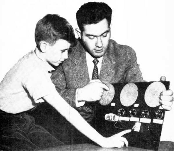
Oliver Garfield, president of the Toy Development Company, Inc., which developed Geniac, explains its workings to Tim Scully, 9, who assembled a circuit unaided, following kit instructions.
This diagram shows how Geniac solves "the problem of the hall light." Verbal statements are broken down into algebraic symbols which, in turn, indicate the number and type of circuit components required.
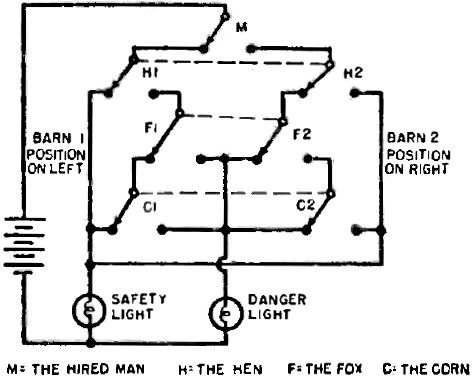
The Geniac circuit shown above represents a robot watchman. It warns the farmer when his corn is in danger of being eaten by the hen. It also warns him when the hen is in danger of being devoured by a fox. Circuit takes into account the possibility that the hired man may not be present at all times to prevent trouble. This ingenious circuit also informs the farmer when all is safe. By the use of ingeniously designed parts, such as a new type multiple switch and special circuit jumpers, the kit provides circuits that "act out" or "prove" the truth of verbal statements about certain situations. One of the most popular of these circuits is the machine for the two jealous wives, illustrated here. In this problem, a "brain machine" must be devised that will inform either or both wives of unfaithfulness on the part of their husbands. Mathematical basis for the Geniac circuits is the application of "Boolean algebra" to circuit design. George Boole, a nineteenth century British mathematician, evolved a system of logic in which symbols represent specific possibilities of things happening one way or another, such as A and B, or, A or B, etc. Certain types of information, when stated verbally, can be analyzed and reduced to simple statements. These statements, or "elements," are, in turn, expressed in symbols. The symbolic statement or "formula" then represents the verbal statement. From the symbols, it can be determined what circuit components are needed and how, to a large extent, they must be arranged in order to provide a circuit that "acts out" the original statement. The gigantic computers that solve complex problems in the twinkling of an eye are based, in part, on these principles. A good illustration of how this system works is the problem of the hall light, one of the circuits included in the kit. The problem, stated in normal language, is this: a man wants to turn off or turn on a hall light either from downstairs or from upstairs. A circuit must be devised so that if either switch is turned the light will go off if it was on, and will go on if it was off. This is a practical problem and involves a kind of wiring that may be familiar to many readers. It implies a switching arrangement in which either of two switches may be "off" or "on" in any position, depending on the relative position of the other switch. The circuit solution to this problem evolves logically from stating the problem in Boolean symbols. U represents the upstairs switch in one position, and D represents the downstairs switch in the same relative position. U-D represents the two switches in series and in positions that permit the flow of current to light the bulb. U' and D' represent both switches in their respective opposite positions. Thus, U'-D' also represents a flow of current. U'-D and U-D' both represent the switches in such relative positions as to break the circuit and permit no current to light the bulb. Stating this in Boolean symbols: U-D v U'-D'. The "v" stands for an expression similar to "and/or" and implies a state of parallelism between the two expressions it connects. Thus, the formula tells us that two series switches are needed in parallel with each other. Since each switch must perform one of two possible functions (the "either -or" element), each switch must be a double-throw switch. The diagram and schematic shown here illustrate this reasoning process. In every application of Boolean logic to a verbal statement, the circuit must prove the truth of the statement. In this case, the final circuit fulfills the requirements of the man with the upstairs and downstairs halls. In other circuits which can be built with the kit, a similar proof is achieved. For instance, the kit may be used to construct an electronic version of tic-tac-toe. Now, anyone who has played this game knows that if you make the first move, regardless of what your opponent does, you must either win or draw, provided you make the best possible move following each of your opponent's moves. In other words, the player who goes second cannot win unless the first player commits an error. The Geniac circuit for this situation is a complex one, but once constructed, proves infallible. In a word, you can't beat the machine! The underlying principles of the Geniac kit have been in development and research for a number of years. One of the best known pioneers in this country in the application of algebraic analysis to the problems of telephone circuitry is Dr. Claude Shannon of Bell Telephone Laboratories, whose "magnetic mouse" was described in the May issue of Popular Electronics. Another noted mathematician, Edmund C. Berkeley, has contributed largely to the development of the Geniac kit. Mr. Berkeley, an exponent of symbolic logic, is the author of the instruction manual that is furnished with the kit. Production of the kit, and the solving of the problems involved in putting it together, is largely the work of the Toy Development Company, of which Oliver Garfield, scientist and teacher, is the head. In addition to its value as a source of amusement and education, the kit exhibits certain technological features that may have widespread implications in other areas. The switches themselves are designed for simplicity and economy. Where the equivalent of several banks is needed, which ordinarily requires a multi-deck or multi-wafer switch built up vertically, the Geniac method uses a single wafer. Contacts on this wafer provide the equivalent -laterally - of what conventionally ganged switches do. This single wafer unit is an exclusive Geniac development, on which patents are pending. Speaking for the Geniac project, Mr. Garfield is quite optimistic regarding its future. New developments may see an electronic I.Q. tester for professional use, as well as improvements in data analysis machines. For additional information, as well as to order kits, write to The Geniac Project, 29 St. Marks Place, New York 3, N. Y.
Posted August 12, 2019 |
|