Understanding Updated FM Tuner Specs
|
|
Since we seem to be on a roll of FM radio theme articles printed in vintage electronics magazine, here is one from a 1973 issue of Popular Electronics. The author never explicitly tells us the date when the Institute of High Fidelity (IHF) updated its FM tuner specifications, and neither does he mention groundbreaking work of IHF's Julian Hirsch, who is largely responsible for both the initial and updated standards. If you read magazine stereo equipment reviews in the 1960s and 1970s, then you probably recall the name. Anyway, this article discusses the improved specifications made possible by more sophisticated circuits made possible by semiconductors and miniaturized passive components. Interestingly, by 1973 magazines had gone from abbreviating decibels from d.b. to dB, from k.c. and m.c. to kHz and MHz, from m.m.v. to (μV), and from r.f. to RF, but they still used i.f. (intermediate frequency) rather than IF. If you know the meaning of the new specs, you'll be able to select the best tuner
The Institute of High Fidelity (IHF), an organization of hi-fi component manufacturers, last issued formal testing standards for basic FM tuners and those in receivers way back in 1958. Though vastly superior to the testing procedures used by manufacturers prior to their issuance, the standards are nevertheless somewhat archaic in terms of today's modern stereo FM tuner. After all, in 1958, all tuners employed vacuum tubes exclusively, and stereo FM broadcasting was three years in the future. Too, FM broadcasters numbered in the hundreds then, and there was generally a good deal of "dial space" between stations. Recognizing that the old standards do not adequately cover or describe the performance of a modern FM tuner, many manufacturers have begun to list specifications not mentioned in the old standards - specs designed to augment the basic facts that were needed in 1958. Happily, these "new" specs are fairly consistent from product to product, permitting the prospective buyer to compare competitive products once he understands the purposes of the new "numbers." In addition, some of the older specs, originally relegated to positions of secondary importance, take on primary status in light of modern tuner requirements, Our purpose here is to examine both the old and the new specs as they relate to a modern state-of-the-art FM tuner. IHF Sensitivity
Fig. 1 - Important FM characteristics are determined from plotted curves such as those shown here. Sometimes known as the "least usable sensitivity," IHF sensitivity is usually the first in a long list of tuner specs. It is defined as the least number of microvolts (μV) of signal needed at the antenna terminals to produce an audio output 30 dB above the background noise and distortion. Now, with the output 30 dB above the distortion, the latter is about 3 percent, which is actually a lot of noise and distortion - an amount you would not tolerate in an amplifier or tape recorder where signal-to-noise specs easily reach 50 dB or more and where residual distortion is usually measured in tenths of a percent. What is worse is that residual noise and distortion when listening to stereo FM is invariably greater than when listening to mono stations, Hence, the 30-dB signal-to-noise ratio and distortion criterion may well turn out to be 20 dB or less when so few microvolts are applied to the tuner for stereo reception. Illustrated in Fig. 1 is how noise and distortion reduce as signal strength increases. Many manufacturers have begun to quote the input signal in μV required for a more realistic 50-dB signal-to-noise ratio which is more "listenable" than the old 30-dB reference. In Fig. 1, this occurs with an input signal of 5 μV, as opposed to an IHF sensitivity figure of only 1.8 μV. Distortion In general, distortion figures for stereo FM listening tend to be a bit higher than they are for mono. The composite stereo signal is much more complex than is a mono signal, and both i-f and detector circuitry must be carefully designed if low orders of audible distortion are to be maintained. In addition to the required total harmonic distortion (THD) figure stated for mono reception, many spec sheets now list THD for stereo as well. Again referring to Fig. 1, you can see that at a 1000-μV input (the point at which most distortion measurements are made) , 0.3-percent THD is shown for mono, while for stereo the THD is 0.8 percent.
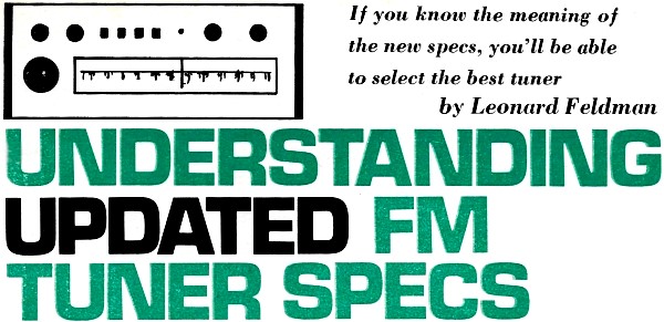
Fig. 2 - Distortion is usually higher when stereo FM signals are received.
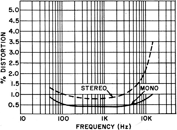
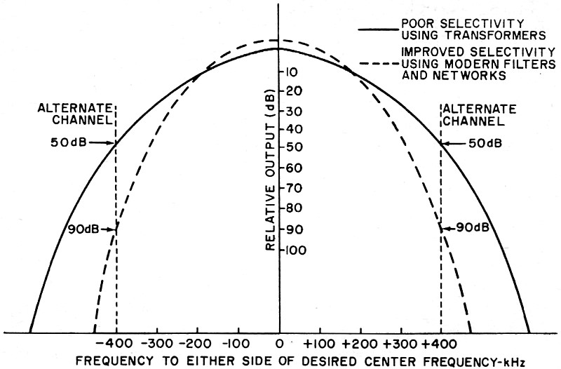
Fig. 3 - Stereo FM separation often varies widely with audio frequency. It is not uncommon for THD to be somewhat higher at extremely low and high audio frequencies than at the mid-frequencies where distortion measurements are usually made. Some of the braver manufacturers have begun to quote figures for several frequencies, such as 100 Hz, 1000 Hz, 5000 Hz and 10,000 Hz, and the really daring ones have begun to quote these THD figures for stereo performance as well. A typical THD-versus-frequency curve is shown in Fig. 2, from which the four THD numbers for mono and stereo can be picked off for a representative tuner. Stereo Separation Most manufacturers have been quoting stereo separation figures taken at 1000 Hz since the inception of stereo FM broadcasting. Frankly, this spec is relatively unimportant unless the figure given is less than 20 dB. After all, even the best stereo phono cartridge seldom has a separation capability much beyond 25 dB, which at high frequencies tends to diminish rapidly. More important is the ability of the tuner to maintain adequate separation at the extreme high and low audio frequencies. Here, too, more quality-conscious manufacturers have begun to list separation figures for frequencies other than the nominal 1000 Hz, and some even publish a complete curve that gives a total picture of separation-versus frequency (see Fig. 3). Selectivity & Capture Ratio Of the two related terms, capture ratio is probably less understood (and more difficult to measure) than is selectivity. The Federal Communications Commission assigns FM frequencies so that no two stations in the same geographic vicinity are on the same or even adjacent channel frequency. Usually within a major metropolitan area, stations will be assigned frequencies as much as 800 kHz apart. Each channel occupies a total bandwidth of 200 kHz. Weaker suburban area stations in a region may be assigned frequencies that are only 400 kHz apart, while 200 kHz separation between stations in a region will be made only for stations deemed to be so far apart that no interference can take place between them. However, the fact is that tuners of late vintage have become more and more sensitive and what was once regarded as a sufficient geographical distance between transmitters may no longer be valid. Capture ratio defines the ability of a tuner to "capture" a desired station while rejecting a more distant or weaker station broadcasting on the same frequency. While such a condition may at first seem remote, remember that the distant station may be many times more powerful than the "local" desired station - a condition that tends to offset, at least in part, the greater distance to the undesired station. Capture ratio is measured and quoted in dB; the lower the number, the better the characteristic. Selectivity, as generally stated in spec sheets, is really an abbreviation for "alternate-channel selectivity," which means the ability of the tuner to reject signals 400 kHz (two channel widths) away from the desired signal frequency. Selectivity is determined primarily by the design of the i-f section of an FM tuner (though the r-f or front-end also plays a part in this characteristic as well). When a manufacturer claims that his tuner is using multi-element (or crystal or ceramic) filters in its i-f section, he is informing you that the tuner's selectivity has been improved. Older, more conventional, i-f transformers were not capable of providing the steep, carefully controlled "bandpass" characteristics required in modern FM tuners. A comparison of the bandpass characteristics of the older and newer forms of i-f circuits are superimposed in Fig. 4 to illustrate the difference between "good" and "not-so-good" selectivity. As with capture ratio, selectivity is quoted in dB, with the higher number indicating the better tuner. Typical Tuner Specifications
Full Limiting & AM Rejection These two terms are also related to each other, with most manufacturers now providing a figure for the latter and some offering a figure for the former. "Full limiting" means that at the required signal level input, the unit works totally as an FM tuner. A further increase in signal level will not produce audio amplitude changes as was the case for signal levels below the full limiting threshold. The primary virtue of any FM tuner is the fact that it rejects or does not respond to changes in incoming signal amplitude (AM). This accounts for its ability to be insensitive to man-made noise and electrical interference, such as ignition noise, lightning and the like, which are AM phenomena. While rejection of these forms of interference has always been recognized as an important virtue of FM, the relationship between AM rejection and "multipath" problems has become more evident with the popularization of stereo FM broadcasting. Multipath in FM is akin to "ghosts" in TV reception. It is caused by reflections from adjacent man-made and natural structures. The primary signal arrives at the antenna at a given time, while reflected signals arrive fractions of a second later because of the greater distances they must travel. Now, these reflected signals may be in-phase, phase-displaced, or even totally out-of-phase with the primary signal when they finally arrive at the antenna. If they are phase-displaced or out-of-phase, they will partly cancel the amplitude of the incoming signal. Varying intensity of all incoming signal is, in effect, AM reception, and if a tuner is incapable of rejecting this form of "AM," you will hear a wavering, whooshing sound, often accompanied by severe distortion that is particularly noticeable when sibilant sounds are articulated or when musical high frequencies are reproduced. While good AM rejection is by no means a cure-all for multipath distortion, it certainly helps (proper orientation of a good directional outdoor antenna is a must). AM rejection is quoted in dB; the higher the number the better the tuner. Full limiting is given in microvolts where the lower the number, the better. Spurious Response & Image Rejection Ideally, when a tuner is set to a frequency of 100.1 MHz, the only signals you should receive are those broadcast on 100.1 MHz. If your listening experience goes back to the early days of FM, however, you have probably run into the problem of "spurious responses" - signals showing up at points on the dial where they just should not be. There are many causes for this problem. Often, close-by powerful transmitters emit signals that are powerful enough to "overload" the tuner and tuning becomes meaningless. At other times, the undesired frequency may be related to the dial setting in some mathematical way so that a signal appears where it should not be.
Fig. 4. Curves show improvement in selectivity through the use of modern filters and networks. Image frequencies are a specific form of spurious response that is quite interesting. The hand of frequencies just above the high end of the FM band (above 108 MHz) is used for, among other things, police and aviation communication. Most FM tuners operate on the "superheterodyne" principle with a built-in oscillator tuned to 10.7 MHz above the desired frequency. The beat or difference between the two frequencies becomes the i-f signal which is amplified and detected by the rest of the tuner's circuitry. Now, suppose the tuner were set for a dial frequency of 105.5 MHz, which means that the local oscillator is tuned to 116.2 MHz (105.5 + 10.7). Suppose, too, that a local aircraft transmitter was transmitting at 126.9 MHz. This incoming signal, if not adequately rejected by the "front end" of the tuner, would mix with the local oscillator to also produce a 10.7 MHz i-f (126.9-10.7). To all appearances, this beat signal is a valid i-f signal that will be amplified and detected by the tuner to produce an undesired output. Consequently, "image rejection" is determined by the design and quality of the r-f front end of the tuner and is quoted in dB where the higher the number, the better. Judging FM Tuner Quality The information given in the Table is this writer's opinion of the kinds of specs you might expect in an "average," a "good," and a "super" tuner these days. The tabulation is intended to be more a general guide than the last word from a great oracle. However, it does include just about every performance spec a manufacturer should include, omitting such entries as control features, "drift" (which should be minimal in any modern, well-designed tuner), and mechanical considerations. If you find that one or more of these specs is not given when you are shopping around, you can write to the manufacturer and ask for it. For one thing, you are very likely to receive an answer; for another, you might prompt the manufacturer (and the industry at large) to be more complete in his future listings. That can only lead toward the much-needed updating of uniform industry standards.
Posted March 16, 2020 |
|