The Capacitor: What It Is, What It Does, How It Works
|
|
Here is a very nice primer on capacitors that appeared in the April 1960 issue of Popular Electronics. A lot of ground is covered including history, form factors, dielectric types (ceramic mentioned as a new variety at the time), applications, etc. Interestingly, units of picofarads (pF) were still being referred to as μμfarads. In fact, since not a lot of work was being done yet in the gigahertz (GHz) realm, there was not much use for pF other than maybe to tune a filter response. Author Ken Gilmore reveals a sense of humor when writing of early capacitance experiments as he says, "Since they couldn't think of much to do with the Leyden jar except stand around and shock each other, they didn't have any need for an accurate system of measuring the stored charge, or the capacitance, of the jar." The Capacitor: What It Is, What It Does, How It Works
The capacitor was invented in 1745 by experimenters who were looking for a way to "condense" and store that newly discovered curiosity, electricity. Although many of their ideas were wrong, they came very' close to doing what they set out to do! Today's modern capacitor comes in thousands of different sizes, shapes, and colors. It is of vital importance in the operation of everything from the family car to guided missiles; yet it does exactly the same thing and works on the same principle as its remote ancestor discovered in a laboratory at the University of Leyden over two centuries ago. Storing the Charge - What Is a Capacitor? A great bolt of lightning crashes to earth with an ear-splitting clap of thunder. This is perhaps the . most dramatic demonstration of capacitance at work. A guided missile streaks into the heavens on a column of flame. Without capacitors doing hun-dreds of different jobs in its guidance, control, and firing systems, it would never leave the ground. Your radio and television sets bristle with capacitors used in dozens of different ways. Radio and TV broadcasting stations use thousands of them.
Capacitors set off photographers' flash bulbs, help deliver electric power efficiently to your home, automatically start water fountains and open doors as you approach them. What is this strange phenomenon of capacitance that surrounds us on every hand? How does it work? What causes it? What does it do? The answer sounds almost too simple. A capacitor is a device that can store an electrical charge. Because of this seemingly modest accomplishment, it can perform an astonishing variety of jobs and is one of the most important of our electrical and electronic servants. Capacitive Operation - How a Capacitor Works Did you ever walk across a carpet on a cool, dry day and feel a spark jump from your fingers to the door knob as you reached to open the door? Whether you knew it or not, your body was one part of a charged capacitor; the walls of the room - including the door and the door knob - were the other part. You built up the electrical charge by walking across the rug. The friction between your shoes and the rug deposited excess electrons on your body, each one helping to build up a higher and higher negative charge. Simultaneously, a positive charge of exactly the same strength was accumulating on the walls. When you got close to the door, the capacitor was discharged. The excess electrons in your body leaped across space between your fingers and the door knob to neutralize the charge. The capacitor formed by your body and the room is very different from the ones used in radio, but it works in exactly the same way. A radio capacitor is usually made of two or more metal plates, parallel to each other, but not touching. They are charged, not by rubbing them across a carpet (it could be done that way, but there is a better method), but by connecting them to a battery with a switch as shown in the diagram to the right. Charging the Capacitor
Soon, the battery has moved all the electrons it can. The flow stops; the capacitor is fully charged. If it were now disconnected and the voltage across it measured, by a very high impedance meter, it would equal the battery voltage. The capacitor actually stores the energy in its dielectric, that is, in the insulating material between the metal plates. The dielectric can be air or any other insulator.
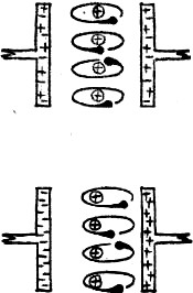
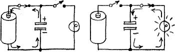
Practical capacitors are manufactured with dozens of different kinds of dielectrics, This theoretical view shows how the charge is stored. In an uncharged capacitor, the number of free electrons in either plate is the same. The electrons in the molecules of the dielectric can be seen orbiting around their nuclei. When a charge is applied, the picture changes. The negative plate now has all of the free electrons. Since it is a basic law of electricity that like charges repel each other, and unlike charges attract, the orbiting electrons in the dielectric are repelled by the negative plate and attracted by the positive one. They move as far toward the positive plate as they can, which stretches the molecules of the dielectric out of shape. These misshapen molecules are like springs under tension: they try to pop back to their normal shape. As long as the charging voltage is applied, they can do nothing. But if a conducting path is sup-plied between the two plates, the dielectric molecules will snap back, pushing the excess electrons out of the negative plate, and discharging the capacitor. The voltage storing ability of a capacitor is called capacitance. You may sometimes hear it called capacity, but capacitance is grammatically correct. Firing a Flash Bulb Of what practical use is a capacitor's ability to store a charge? Photographers use it in one of the simplest and most obvious ways. In one type of flash gun, they charge a capacitor, then connect a flash bulb across its charged plates. All the electrons stored on the negative side try to rush to the positive plate at one time, through the flash bulb. This surge of current fires the bulb. (See the circuits at the top of the next page.)
Why not connect the battery directly to the bulb? This could be done if a large enough battery were used. Such a heavy-duty battery could deliver enough current to fire the flash bulb. But a far lighter, more compact unit weighing only a few ounces can be made to do the same job with the help of a capacitor. A battery capable of putting out only a trickle of current - far less than would be required to set off the bulb - can be used. Over a period of time, the trickle builds up a powerful charge across the capacitor, in the same way that a tiny stream of water can eventually fill a large tank. When the capacitor is fully charged, it can deliver a surge of current even more powerful than the heavy battery, and thus easily fire the flash bulb. Positive and Negative A great deal has been said about "positive" and "negative" charges. But did you ever stop to think why one pole of a battery is called positive and the other negative? It's all a mistake, really, because the one we call negative is actually positive, and the one we call positive is... But maybe we should start from the beginning. Old Ben Franklin made the original mistake. Nobody knew for sure in which direction current flowed. So Franklin guessed. He named one pole positive, the other negative, based on the reasoning that current went from the positive pole, which he visualized as having an excess of current, to the negative pole, which had a shortage. He had a fifty-fifty chance of guessing right, but luck was against him. Many years later it was established that current actually flows in the other direction. By that time, positive and negative terminology was firmly established and it was decided that no change would be made. Whether the labels are right or wrong, polarity is an important consideration in many capacitor circuits. For example, the electrolytic capacitors used in power supplies will be ruined if they are connected with the wrong polarity. Capacitors in Power Supplies
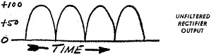
Capacitive "filters" are frequently used in power supplies to smooth out the pulsating d.c, output from an a.c, rectifier circuit, thus allowing 117-volt house current to be converted into direct current. Without a capacitive filter, a power supply produces pulsating direct current. The current Bows in only one direction, but not steadily. A picture of pulsating d.c. from a full-wave power supply looks like this:
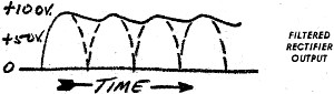
But radio and TV receivers need a source of pure d.c, that rises to a certain voltage level and stays there. A capacitor connected across the power supply gives just this effect. As the voltage rises to maximum, the capacitor becomes charged. When the power supply voltage falls to zero again, the capacitor begins to discharge, and helps keep the voltage near its maximum level until the following power supply surge, which charges the capacitor again for the next cycle. You may notice that the voltage does not remain exactly at the maximum level during the capacitor discharge. But if circuit components of the proper values are selected, it stays close enough so that the difference is unimportant. It is easy to tell when the filter capacitor (or capacitors) in your radio are going bad. As the capacitor starts to fall down on the job, the ripple gets bigger and bigger. Soon it begins to affect the operation of the whole set, and you hear a loud hum. As it gets worse, speech and music become distorted or garbled; then a heavy hum is about all you can hear. Applications in A.C. Circuits
The two examples of capacitor use mentioned so far - photo flash and filter - deal with d.c. voltages and currents. But a capacitor's function in a.c. circuits is perhaps even more important. To understand how it works, let's take a look at the two plates and battery setup again. Only, this time, they are connected - by a double-pole, double-throw switch, that is, a switch that can quickly reverse the polarity of the charging current applied to the capacitor. With the switch thrown to the left, the capacitor charges. Open the switch, and the capacitor retains its charge. The switch is now thrown to the right. This connects the capacitor to the battery again, but with the polarity reversed; the negative plate is now connected to the positive battery terminal and vice versa. The electrons quickly flow through the battery from the negative plate to the positive one, discharging the capacitor. It then charges again, but this time with opposite polarity. The ammeter shown connected in series with one plate will indicate current flow during this process.
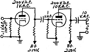
With the switch to the left, the meter will show a current flowing while the capacitor is charging. When the switch is reversed, the meter indicates a current in the opposite direction while the capacitor discharges its old charge and takes on the new one. If the switch is thrown back and forth fast enough, the meter will show current flowing at all times - first in one direction, then the other. Thus, it is clear that even though direct current cannot flow in a capacitor circuit (except during a brief charging period), alternating current can be made to flow continuously by alternately charging and discharging the capacitor. To put it another way, a capacitor "blocks" d.c., but "passes" alternating current. This ability is put to work in countless ways. Here, for example, is a simplified amplifier circuit that demonstrates the effect. The signal is introduced into the tube's grid circuit, is amplified, and leaves through the plate circuit. For the tube to work, the plate must be kept at a high positive voltage-say 200 volts-while the grid must be slightly negative. Since electron tubes usually operate with a high positive voltage on the plates and a low negative voltage on the grid, the problem obviously arises: how can the tubes be coupled together plate-to-grid without disturbing their respective d,c, operating levels? The capacitor is made to order for this job. Since the signal to be amplified is a.c., it will pass through a capacitor easily, while the d.c, operating voltage will be blocked. A capacitor used in this way is called a coupling or blocking capacitor. Either name is correct. A capacitor's ability to pass a.c. while blocking d.c, is also useful in another kind of hookup. For example, signals frequently appear where they aren't wanted. A capacitor can "short" such an unwanted signal to ground while leaving the circuit's d.c, voltage unaffected. This is called "by-passing." Versatility Unlimited - Values, Types, Uses of Capacitors The capacitor was invented back in October, 1745, by Dean E. G. von Kleist of the Kammin Cathedral in Pomerania. A few months later - in January, 1746 - Pieter von Musschenbroek, a professor at the University of Leyden, made the same discovery all over again. Somehow, Musschenbroek got the credit, and early capacitors were called Leyden jars after his university. You may have seen one around a physics laboratory; they're still used at times to demonstrate the principle of capacitance. The Leyden jar is simply a bottle with about three-quarters of both the inside and outside surfaces covered with metal foil. The two pieces of foil are insulated from each other by the glass dielectric. A brass rod goes through a stopper and makes contact with the inside foil. Early experimenters used a jar because they were looking for a way to "condense" and store electricity. Since they thought of electricity as a fluid, they figured a jar would be just the thing to hold it. The name condenser, which is still frequently used instead of capacitor, comes from these early attempts to condense electricity. Musschenbroek and his associates discovered that if they touched the brass rod of the Leyden jar to an "electric machine" (they had a crude electrostatic generator), the jar retained a charge. You could get a shock by holding the outer foil with one hand and touching the rod with the other. Since they couldn't think of much to do with the Leyden jar except stand around and shock each other, they didn't have any need for an accurate system of measuring the stored charge, or the capacitance, of the jar. As the science of electricity progressed, it became obvious that a system of measurement was needed. So a basic unit of capacitance was decided on. It was named the farad, after Michael Faraday, one of the great electrical pioneers. A farad represents a specific amount of "storing power" or capacitance. In actual use, the farad turned out to be far too large a unit, so practical capacitors are usually rated in microfarads (mf.) - one millionth of a farad, and in micromicrofarads (mmf.) - one millionth of a microfarad. (According to one system of notation, a "μ" is substituted for "m" in the abbreviation. Thus, "mf." becomes "μf." and "mmf." becomes "μμf." The meaning in either case is the same.) To put it another way: 1 mf. (or μf.) = .000001 farads 1 mmf. (or μμf.) = .000000000001 farads
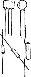
Capacitor Variables The capacitance of any capacitor is determined by four factors. Let's take a look at each one. 1. Size of plates. Large plates can hold a greater charge (more electrons) than small plates. 2. Separation of plates. The closer together the plates are (without touching), the greater the charge they can store. 3. Number of plates. The more plates, the greater the capacitance. 4. Dielectric constant. Every different dielectric material has its own dielectric constant. Air has an arbitrarily assigned constant of 1. Mica has a constant of about 7. This means that mica will store about seven times the charge that air can handle, with all other factors the same. Paper has a dielectric constant of about 5, and some types of ceramic over 1000! Different substances have different constants because each molecule has a different "natural elasticity," which allows some to store vastly greater amounts of energy than others. Among frequently used dielectrics are plastics of various kinds, air, mica, and paper. Types of Capacitors Here are some of the more common types of capacitors, classified according to dielectric material.
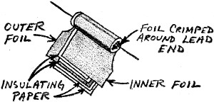
Paper capacitors are made of long strips of aluminum foil, wrapped tightly in a roll, separated by a paper dielectric. To make the paper a better insulator (to prevent breakdown of the capacitor when high voltage is applied to its plates), it is usually impregnated with oil, wax, or plastic. Plastic capacitors are similar, but use thin sheets of plastic - Mylar and others - as a dielectric. They have the same uses and are about - the same size as paper capacitors. Metallized paper capacitors are another variation of the same basic type. Instead of strips of aluminum foil, this capacitor's plates are microscopically thin layers of metal deposited by an evaporation technique on the dielectric paper. Because the plates are so thin, the capacitor can be rolled into a very much smaller package than a standard capacitor of the same capacitance. All of these variations of the paper capacitor are widely used in coupling, bypass, and tone control circuits. They are usually tubular, and range in capacitance from about 250 μμf. to 1.0 μf. or more. They have voltage ratings up to about 1600 volts - that is, they can withstand 1600 volts without the voltage breaking through the dielectric and destroying the capacitor. Most used, however, are capacitors in the 400-600 volt range. Minor differences exist between the various types. Plastic capacitors can be built more easily to withstand higher voltages. Metallized ones, as mentioned earlier, are smaller, and they cost more. With these exceptions, the three types are generally interchangeable. The printed band around one end of these tubular capacitors tells you which lead is connected to the outer layer of foil. In general, the lead so marked should be connected to the "low" side of the circuit. To put it another way, connect it to ground if possible, or to the side of the circuit electrically closest to ground potential. The band does not indicate the polarity of the connections. When a capacitor is used this way, the outer layer of foil serves as an electrostatic shield, so that the capacitor's operation will not be affected by other stray fields within the circuit. Oil capacitors also use a layer of paper as a dielectric; the paper is impregnated with a special type of oil that gives it both a high capacitance and a high voltage rating. They are usually used as high-voltage power supply filters. Capacitance varies from 1.0 μf. to 20.0 μf. or more. Oil capacitors are usually sealed in a heavy can, and may have a rating of 1000 volts or more.
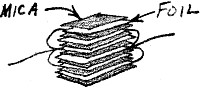
Mica capacitors are made of a number of flat strips of metal (tin, copper, aluminum, etc.) separated by sheets of mica. Alternate plates are hooked together, and the whole assembly is molded into a block of plastic or ceramic material. They range in capacitance from about 10 μμf. to .01 μf. Mica is an unusually good insulator, so capacitors with a mica dielectric can be built with ratings up to 5000 volts or more, and are used in high-voltage transmitting circuits.
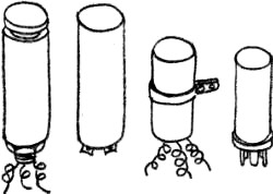
Ceramic capacitors, a newer type, use sheets of ceramic as a dielectric. The plates are normally vapor-deposited silver. A ceramic capacitor generally has only two plates - one on either side of a ceramic disc, or one on the outer and one on the inner surface of a ceramic tube. Since ceramic has a very high dielectric constant, up to 1200, relatively large values of capacitance can be obtained with small capacitors. Also, the insulation quality of ceramic is excellent, so these units can easily be designed to operate at several thousand volts. They are widely used in television, military and satellite communications equipment, and other critical circuits. Advanced manufacturing techniques have brought the cost of ceramics down to about the same range as paper. They have one disadvantage: they are not as readily available in the larger common values. Electrolytic capacitors pack the largest amount of capacitance into the smallest space. They come in sizes up to several thousand microfarads, with working voltages up to about 600 volts. The cans an inch or more in diameter and four to six inches long that are mounted on top of almost every radio and TV chassis are electrolytic capacitors. They are usually used as power supply filters. Electrolytics have extremely high capacitance values because the dielectric is only a few millionths of an inch thick. The capacitor is manufactured by dipping an aluminum sheet into an electrolytic solution, and setting up a current flow from the solution to the aluminum. The action of the current builds up a layer of oxide on the plate. When the layer is completely formed, the aluminum is ready to become the positive plate of a capacitor. The dielectric - the oxide coating - is already in place. The unit is sealed in a can filled with a conducting liquid which becomes the negative plate of the completed capacitor.
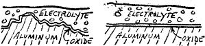
This is a description of the so-called "wet" electrolytic. There is also a "dry" electrolytic. The only difference is that the "wet" uses an actual solution, while the "dry" has a saturated layer of gauze between the plates. In actual use, the wets have almost disappeared, because drys are more convenient to manufacture, store, and use. Electrolytics, like most other components, are getting smaller and smaller in this age of miniaturization. A recently developed type - the etched aluminum electrolyte - packs even greater capacitance into a smaller volume by using a plate that has been roughened by chemical etching. A greatly magnified cross section of the etched aluminum would compare with the usual polished surface like this:
Obviously, the etched plate has a far greater surface area exposed to the electrolyte, and consequently has greater capacitance. The etched aluminum capacitor is now on the market, but is considerably more expensive than the ordinary electrolytic. Its extra cost is, of course, well worth the difference in such diverse applications as hearing aids and missiles, where weight and size are very important. Electrolytics have several disadvantages. One is that leakage current is larger than for any other type. The other is that the electrolytic has a positive and a negative terminal. Therefore it cannot be used where the polarity changes (in a.c, circuits, for example). Great care must be taken to see that it is properly connected. Even a few seconds ex-posure to the wrong polarity voltage can ruin an electrolytic, or even cause it to explode.
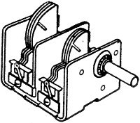
Variable air capacitors are used in every radio for tuning in different stations. One of the sets of plates is fixed to the frame, and is called the stator. The other set, which moves, is called the rotor. Naturally, as in all capacitors. the two sets of plates are close together but do not touch. Capacitance is varied by chang-ing the amount the plates mesh. (There are fixed air capacitors. but they are rare.) Variable air capacitors come in sizes from a fraction of a μμf. to 1200 μμf. or more. Those used in low-voltage receiving circuits may have 10 to 30 plates separated by less than a hundredth of an inch. Large transmitting types can have 80 to 100 plates. separated by a half inch or more. Variable air capacitors are frequently ganged. This means that several independent capacitors are arranged along one shaft so that they rotate together. In this way, several circuits can be tuned simultaneously. Although we have only mentioned fixed mica, paper, oil, ceramic, and plastic capacitors, there are variable capacitors which use some of these dielectrics, too. But most variable capacitors have air as the dielectric. The one common exception to this is the small mica "trimmer" capacitor found in most radio receivers. These units, with a capacitance of only a few μμf., are adjustable with a screwdriver. They are used in making minor adjustments in circuits where the amount of capacitance is critical. The local oscillator in a superheterodyne receiver, for example, is tuned to an exact frequency with a mica trimmer. Only the principal types of capacitors have been listed so far. There are many others: vacuum, glass, vitreous-enamel, polystyrene, tantalum, Milinex, and even one with the jaw-breaking name of polytetrafluorethlene. Each has its own advantage and special uses. And some, like tantalum, are becoming more popular. Willing Workhorse
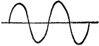
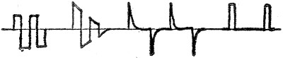
The many ways mentioned so far in which capacitors are, used hardly scratches the surface of the jobs to which this versatile component is suited. Every radio, television, or communications transmitter or receiver, for example, must operate on a certain predetermined frequency. The signal sent out by the transmitter must oscillate, or vibrate, at a precise rate - so many times a second. Receivers must be tuned to this exact frequency to pick up the signal. Capacitors play an important part in circuits which determine operating frequency. Vary the capacitance, and the frequency changes. When you tune your radio, you are adjusting the capacitance of the tuning circuits. Another important duty of the capacitor is wave-shaping. The most common waveshape is the sine wave. The electrical power that comes into our homes is in this form; this is also the shape of an ordinary oscillator's output. But for certain uses - radar, television, telemetering, to name only a few - waveforms of many shapes must be produced.
These and thousands of other waveshapes can be formed by hooking capacitors together in different combinations with other components. Heavenly Charges Oh, yes, one more thing. What does capacitance have to do with lightning? In stormy weather, air currents rise swiftly. Particles of water vapor in clouds are swept past other stationary particles, and a charge accumulates by friction, just as it does when shoes rub across a carpet. The charge on the clouds, small at first, builds up rapidly. At the same time, a similar - but opposite - charge builds up on the ground under the cloud. As the cloud races across the sky, the charge moves along the ground with it - it can be measured with the proper equipment. Higher and higher builds the charge, as more particles of water vapor rush by, each adding to the charge. First, it can be measured in volts, then millions, next trillions of volts from cloud to earth. Finally, the giant capacitor - the cloud forming one plate, the earth the other - "breaks down." The charge arcs over the insulating dielectric (air) and a blinding flash lights up the heavens. The mammoth capacitor discharges in a brilliant flash of lightning. Capacitance - the simple ability of two bodies to store an electrical charge - is thus responsible for one of our most useful electrical components, and at the same time, for one of nature's most spectacular displays.
Posted February 3, 2020 |
|

 By Ken Gilmore
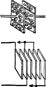 Neither your electric refrigerator nor your
car would start without capacitors; your fluorescent lights would remain dark.
Neither your electric refrigerator nor your
car would start without capacitors; your fluorescent lights would remain dark.
 With the switch open, there is no charge across
the plates. When the switch is closed, the battery's positive terminal begins to
attract free electrons from the plate connected to it, while at the same time the
negative terminal starts to force large numbers of excess electrons into the plate
connected to it. More and more electrons pile up on the plate, making it continuously
more difficult for the battery to force any more on to it. Thus, one plate takes
on a negative charge, the other a positive charge.
With the switch open, there is no charge across
the plates. When the switch is closed, the battery's positive terminal begins to
attract free electrons from the plate connected to it, while at the same time the
negative terminal starts to force large numbers of excess electrons into the plate
connected to it. More and more electrons pile up on the plate, making it continuously
more difficult for the battery to force any more on to it. Thus, one plate takes
on a negative charge, the other a positive charge.